 |
|||
|
|
|||
|
Page Title:
SUPPORT LEG, DRAWBAR, AND REFLECTORS |
|
||
| ||||||||||
|
|
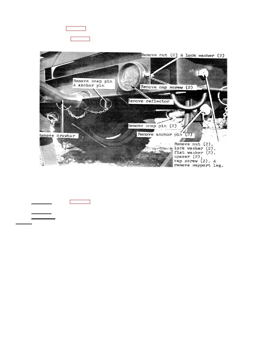 B. SUPPORT LEG, DRAWBAR, AND REFLECTORS
a. Removal - Refer to Fig. 3-11 and remove the support leg, drawbar, and the four reflectors.
b. Inspection - Inspect and replace damaged or missing components as necessary.
c. Inst-ll1tion - Refer to Fig. 3-11 and reinstall the support leg, drambar, and the four reflectors.
FIGURE 3-11. SUPPORT LEG0, DRAWBAR, AND REFLECTORS
C. FRONT ENGINE BRACKET
a. Removal - Refer to Fig. 3-13 and remove the engine. Remove the three cap screws, six lock washers, and
three nuts which secure the front engine bracket to the frame.
b. Inspection - Inspect for broken or weak welds. Repair or replace as necessary.
c. Installation - The installation proceedure is the reverse of the removal proceedure.
NOTE: The two lock washers are installed with one lock washer under the head of the cap screw and one lock washer
under the head of the nut.
21
|
|
Privacy Statement - Press Release - Copyright Information. - Contact Us |
