 |
|||
|
|
|||
|
|
|||
| ||||||||||
|
|
 respective shaft so that the hub face is flush with the shaft
end (fig. 6-5).
(2) Check gap and angular alignment with a
spacer bar. Gap should be exactly 1/8 inch between the
hubs as measured at 90intervals.
(3) Check offset alinement. Aline shafts so
that a straightedge will rest squarely on both hubs at the
top and also at 900 on either side.
(4) After coupling hubs are alined (para 5-15)
insert gasket through gap and hang it on either shaft.
Pack gap and grooves with lubricant before inserting grid.
(5) Insert grid. It is necessary to spread the
grid slightly to pass over the coupling teeth at the outside
diameter: to minimize this spreading, start grid at either
end and tap into place rung by rung. Do not attempt to
force grid to the bottom of the groove; it will seat readily
after all rungs are positioned. Pack spaces around grid
with as much lubricant as possible in accordance with
current lubrication order. Wipe off excess flush with top
of grid.
(6) Place seals on cover halves and slide onto
ME 4320-243-15/6-2
hubs. Installation will be easier if lube plugs are not in
place, so as to allow trapped air to escape. Position
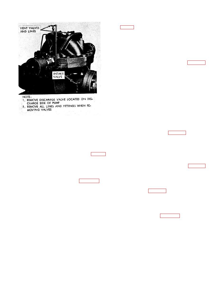
Figure 6-2. Vent, discharge and intake valves, and
covers with lube holes 180 apart and bolt gasket and
lines, removal and installation.
cover halves together, as shown in figure 6-5.
(7) With both lube plugs removed, insert fitting
d. Clean, inspect, and repair.
and fill with grease in accordance with current lubrication
6-5. Pump Coupling
order until an excess appears at the other opening, then
a. General.
The tapered-grid flexible coupling
install the lube plugs.
connecting the engine shaft and pump shaft (fig. 6-5)
utilizes a spring-steel grid coupling member to absorb
6-6. Rotating Element Assembly and Mechanical Seal
engine vibrations. The performance and life of this
coupling depend on proper installation and servicing.
above).
b. Remove and install the pump coupling as directed
b. Disassembly. Unbolt and slide the covers away
in paragraph 332.
from the coupling hubs as shown in figure 6-5. To
remove the grid, use a found rod or pry-bar that will fit
c. Remove and install the
rotating
element
conveniently into the open loop ends, and pry grid out
assembly as shown by figure 6-6.
radially in gradual stages. Proceed alternately from side
d. Disassemble the rotating element assembly in
to side, lifting each loop about halfway out of its slot until
sequence shown by key numbers in figure 67.
the end of the grid is reached. Follow the same
Reassemble in reverse sequence.
procedure once again and the grid will clear the teeth.
e. Disassemble the mechanical seal in sequence
shown by key numbers in figure 6-8. Reassemble in
c. Reassembly.
reverse sequence.
f. Clean, inspect, and repair.
(1) Place hub covers and seals on shaft before
mounting hubs.
Press or shrink each hub on its
6-3
|
|
Privacy Statement - Press Release - Copyright Information. - Contact Us |
