 |
|||
|
|
|||
|
|
|||
| ||||||||||
|
|
 (1) Tag and remove the leads from the switch
terminals.
(2) Disconnect the line from the switch
pressure connection and connect the switch to a source of
pressure that can be varied between zero (0) and 300 psi.
(3) Connect a test lamp circuit between the
common and normally open terminals on the switch, The
lamp should not light.
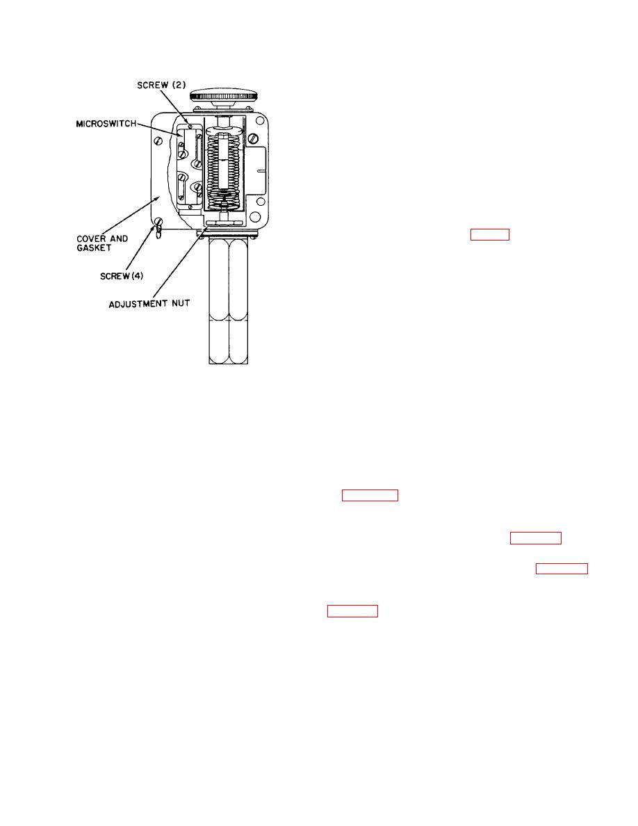
(4) To adjust the switch for series operation of
the pump, slowly raise the pressure on the switch to 250 +
3 psi. The lamp should light. If the lamp does not light,
slowly turn the adjusting nut (fig. 6-1) counterclockwise to
decrease the setting, and cause the lamp to light. Turning
the adjustment nut clockwise will increase the setting.
(5) After making an adjustment, slowly
decrease the pressure until the lamp goes out, and then
repeat step (4).
(6) Repeat steps (4) and (5) until the lamp will
light at 250 + 3 psi on an increasing pressure.
(7) To adjust the switch for parallel operation of
the pump, follow steps (1) through (6) except adjust the
switch to light the lamp at 125 + 3 psi on an increasing
Figure 6-1. Pressure switch.
pressure.
clockwise to increase the setting of the switch. If the lamp
6-3. Throttle Solenoid.
does not light between 110-120 psi, turn the adjustment
nut counterclockwise to decrease the setting.
and low-pressure switches and is also connected to the
carburetor throttle valve.
Excessively high or low
(5) Slowly decrease the pressure on the switch
discharge pressure will activate the pressure switches,
until the lamp lights. The lamp should light at 100 + 3 psi,
thus tripping the throttle solenoid to idle the engine.
on a decreasing pressure. If the lamp does not light at
b. Remove and install the throttle solenoid as shown
100 + 3 psi, turn the adjustment nut clockwise to increase
by figure 3-14.
or counterclockwise to decrease the setting.
6-4. Upper Case.
(6) Repeat steps (4) and (5) until the lamp will
a. Remove and install the vent line, valves, and fluid
light at 100 + 3 psi, on a decreasing pressure.
lines from the upper case as shown by figure 6-2.
(7) To adjust the switch for parallel operation of
b. Remove and install the upper case and casing
the pump follow steps (1) through (6) except adjust the
studs in sequence shown by key numbers in figure 6-3.
switch to light the lamp at 55 + 3 psi on a decreasing
pressure.
c. During installation of the upper case, tighten
fastening bolts in sequence shown by key numbers in
d. Adjust the high pressure switch (fig.
61) as
follows:
6-2
|
|
Privacy Statement - Press Release - Copyright Information. - Contact Us |
