 |
|||
|
|
|||
|
|
|||
| ||||||||||
|
|
 TM 5-4320-237-15
(3) Inspect the discharge hoses
for
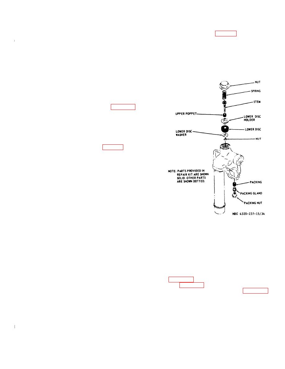
d. Reassembly. Refer to figure 34 and re-
cracks, leaks, signs of deterioration,
assemble the nozzle.
worn or damaged fittings, and other
Pull out on the coupling
e. Installation.
damage.
operating levers and position the nozzle on
(4) Inspect the discharge tee and inlet
the hose. Push in on the operating levers to
adapter for damage which could af-
join the pads
fect the sealing characteristics of the
part.
(5) Check that every female connector
has a mating plug and that every
male connector has a cap to prevent
entry of dirt. Replace all damaged
and missing parts.
c. Installation. Refer to figure 33 and in-
stall hoses and fittinings
69. Nozzles
a. Removal. Pull out on the coupling op-
crating levers to remove the nozzle from the
hose.
b. Disassembly. Refer to figure 34 and dis-
assemble the nozzle.
c. Cleaning and Inspection.
(1) Discard the removed parts for which
there are replacement in the nozzle
repair kit.
(2) Clean all remaining parts with an
approved cleaning solvent; dry thor-
oughly.
(3) Inspect the nozzle parts for cracks,
distortion. worn or damaged threads,
and other damage; replace damagd
parts. Make sure the ground cable
and pinch-type ground connector
are attached and in good condition.
Section XII. PUMP ASSEMBLY
head to prevent fluid from leaking around
70. General
the rotating shaft.
A coupling head provides the adapter to se-
71. Pump Assembly
cure the pump housing and engine together.
a. Housing and Tool Boxes Removal. Refer
One side of the coupling head bolts to the
to figure 35 and remove the pump housing,
power takeoff end of the engine. The pump
and to figure 38 and remove the tool boxes.
housing bolts to the opposite side of the cou-
b. Pump disassembly. Refer to figure 36
pling head. The pump impeller is threaded
and disassemble the pump.
and screws directly to the power takeoff end
c. Cleaning and Inspection.
of the engine crankshaft. Impeller-to-body
(1) Clean all pump parts with an ap-
clearance is regulated by shims between the
proved cleaning solvent; dry thor-
coupling head and body. A seal is installed
between the engine shaft and the coupling
oughly.
|
|
Privacy Statement - Press Release - Copyright Information. - Contact Us |
