 |
|||
|
|
|||
|
|
|||
| ||||||||||
|
|
 TM 5-4320-237-15
(2) Inspect the impeller for cracks, wear,
e. Tool Box and Housng Installation. R e -
fer to figure 38 and install the tool boxes, and
scoring, damaged blades, worn or
to figure 35 and install the pump housing.
damaged threads, distortion or other
damage.
(3) Inspect the pump housing for cracks,
scoring caused by a rubbing impel-
ler, worn or damaged threads, or
other damage.
(4) Inspect the coupling head for cracks,
broken mounting flanges, damaged
seal seat, or other damage.
(5) inspect the seal parts for warping or
deterioration. Carefully check the
seal faces for scratches or scoring. If
any seal parts are damaged, replace
the entire seal.
(6) Inspect the attaching hardware for
cracks, worn or damaged threads,
distortion, or other damage; replace
all damaged parts.
reassemble the pump.
removal and installation.
Section XIII.
(2) Inspect the engine for missing com-
72. General
ponents and visible damage. Using
The engine is secured to studs on the
the starter rope, turn the engine
pumping unit base. The engine unit can be
crankshaft over slowly and check for
removed as a complete operating assembly
scraping or binding.
ready to run, since no disassembly of engine
(3) With the ignition switch in the OFF
parts is required for removal.
position to prevent engine starting,
turn the engine crankshaft over with
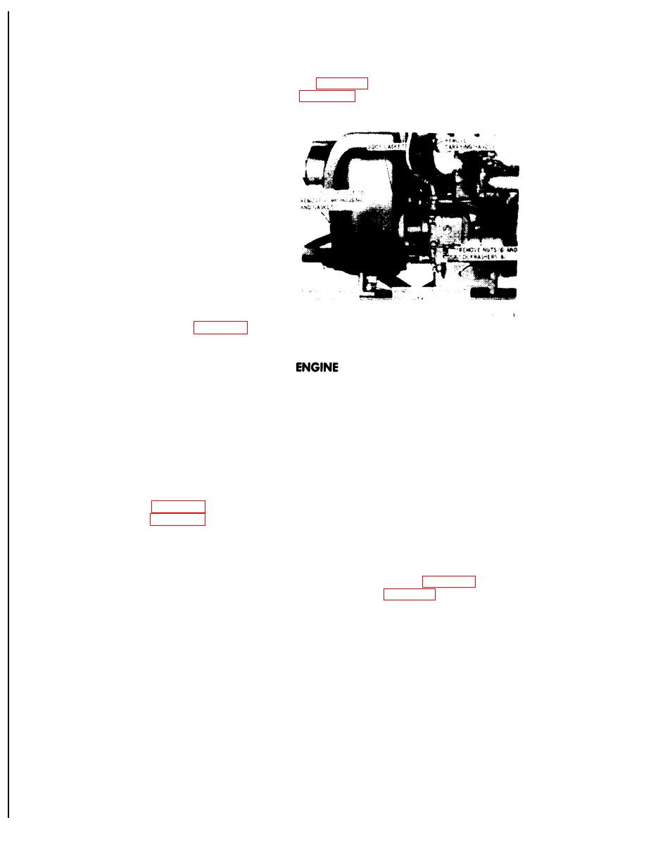
73. Engine
the starting rope to check for com-
pression.
(4) If normal compression resistance is
the tool boxes, and to figure 37 and remove
not noted, or if engine binds or
the engine.
scrapes when the crankshaft is ro-
b. Cleaning and Inspection.
tated slowly, report to direct support
maintenance.
(1) Clean the engine with a cloth damp-
c. Installation. Refer to figure 37 to install
ened with an approved cleaning sol-
the engine, and to figure 38 to install the tool
vent; take care to remove all greasy
boxes.
and oily deposits.
|
|
Privacy Statement - Press Release - Copyright Information. - Contact Us |
