 |
|||
|
|
|||
|
Page Title:
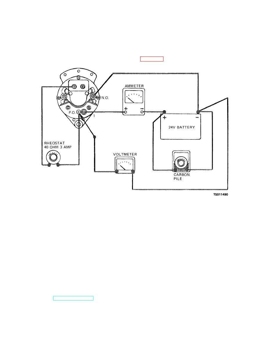
Figure 3-11. Alternator bench test circuit. |
|
||
| ||||||||||
|
|
 TM 5-4320-234-34
(1) Mount the alternator in a test fixture
Secure the diode with nuts (24).
capable of providing 3000 rpm.
g.
Bench Test.
The following test will
(2) Connect fixture circuit leads and
determine the current producing capability of the
instruments to the alternator terminals as shown in
repaired alternator.
Figure 3-11. Alternator bench test circuit.
(3) With the carbon pile turned off to avoid
If you have determined by testing (TM 5-4320-
discharging the battery, set the field rheostat in
234-12, para 4-39) that the voltage regulator should be
maximum resistance position.
adjusted to suit your operating conditions, proceed
according to either of the following methods.
(4) Start the test fixture, and operate at
1500 rpm for a few minutes to normalize operating
a.
You can change the voltage approximately
temperature.
0.6 volt higher or lower by using a metal strap provided
on the underside of the regulator case. Raise the
(5) Increase the alternator speed to 3000
voltage 0.6 volt by placing the metal strap across the
rpm and, at the same time, apply the carbon pile load to
terminals marked HI. Secure strap with the terminal
the battery to keep the charging voltage below 28.0
nuts. Lower the voltage 0.6 volt by placing the metal
volts. At 3000 rpm, the alternator should provide a
strap across the terminals marked LO.
minimum current output of 28 amperes.
b.
If the step adjustment described above did
(6) The charging voltage can be adjusted
not give the exact system voltage you desire, follow this
by the voltage regulator when the alternator is installed
procedure:
on the engine.
(1) With the engine off, connect a
h.
voltmeter to the battery and connect an ammeter in
procedures given in TM 5-4320-234-12, para 4-38.
series with output of the alternator as shown in figure 3-
12.
3-18. Voltage Regulator Adjustment
3-14
|
|
Privacy Statement - Press Release - Copyright Information. - Contact Us |
