 |
|||
|
|
|||
|
Page Title:
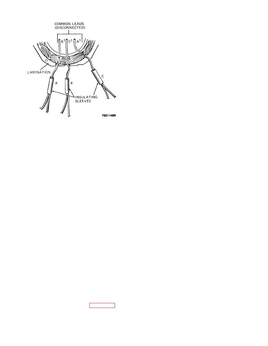
Figure 3-10. Stator test points. |
|
||
| ||||||||||
|
|
 TM 5-4320-234-34
(1) Make certain that all positive and
negative rectifier diodes are soldered to the proper
stator leads and that the stator common leads have
been resoldered together after testing.
(2) Press the bearing (31) into the front
housing (32), using a driver tool that exerts pressure on
the outer bearing race only. Place the bearing retainer
(30) in recess, making certain the retainer ears line up
with openings in the housing. Use a wooden dowel to
exert pressure on the retainer when you seat its edge in
the recess.
(3) With the rotor leads in position on the
rotor assembly (46), carefully press the rear bearing (45)
onto the rotor shaft, exerting pressure on the inner race
only.
(4) Guide the rotor winding leads through
the square passage in the slip ring hub. Hand press the
slip rings (44) onto the shaft while you maintain
alinement of rotor leads and passage. Install screw (42)
and washer (43) and tighten to 45 inch-pounds. Before
Figure 3-10. Stator test points.
soldering the rotor winding leads to the slip rings, make
(3) The resistance should be infinite or test
certain that fiber insulating washers are in place on the
lamp should not light in all of the above tests. If the
inner slip ring terminals.
Wrap leads around the
resistance reading is not infinite or in the test lamp lights
terminals and solder with rosin core solder. Secure
in any test, high leakage or a short exists between stator
wires to the end of the rotor and slip rings with a
windings, or between a stator winding and the
synthetic rubber sealer. Retest the rotor circuits to
lamination. Replace the stator.
ensure that a short or ground did not develop during
(4) Test for stator continuity by connecting
repair. Refer to subparagraph e(5) above.
the ohmmeter or test lamp probes to each pair of the
(5) With the rotor properly supported on an
following test points:
arbor press, use a driver sleeve on the inner bearing
Point A to point A
race and press the front housing (32) onto the rotor.
Point B to point B
(6) Position the spacer (21), fan (19), and
Point C to point C
pulley (18) in place on the rotor shaft. Secure with the
You should have a reading of approximately 0.1 ohm or
lock washer (17) and nut (16). Tighten to 35 foot-
the test lamp should light in each test.
Infinite
pounds torque.
resistance or an unlighted test lamp indicates an open
(7) Position the insulating washers (39)
winding. Replace the stator if it fails any of the above
and sleeves (38) on the studs of the diode assemblies
tests or, if the alternator has been disassembled
(36 and 37). Position the diode assemblies in the rear
because of an electrical malfunction, replace the stator
housing so that the washers and sleeves electrically
after all other components have been checked and
insolate the diode assemblies. Secure with insulating
found to be satisfactory.
washers (35) and nuts (34).
(5) Use a multimeter to test the rotor and
(8) With rear bearing retainer (40) in place,
slip ring assembly. Connect the slip rings in series with
position the rear housing (41) over the slip ring end of
a multimeter and a 20-volt supply. There should be a
the rotor and hand press the housings together. Aline
1.20- to 2.5-amp current draw. Your multimeter should
the slots in the stator with the openings in the housings
indicate 11 to 14 ohms resistance across the slip rings.
and install the through bolts (29). Install nuts (28) and
Connect one of the multimeter or test lamp probes to
tighten to 50 to 60-inch pounds (6.9150 to 8.2980 kgm)
the rotor body and the other on either slip ring. You
torque. Turn the rotor by hand to check for binding of
should have an infinite resistance reading or the test
bearings. Rotor must rotate freely.
lamp should not light. If this does not occur, then either
(9) Install the isolation diode (26), noting
the slip rings, ring connecting leads, or rotor winding is
the proper position of the plate insulators (25, 27, and
grounded. Replace a faulty rotor.
35).
f.
Reassembly. Reassembly is essentially the
reverse of disassembly. Refer to figure 3-7. Pay
particular attention to the following:
3-13
|
|
Privacy Statement - Press Release - Copyright Information. - Contact Us |
