 |
|||
|
|
|||
|
Page Title:
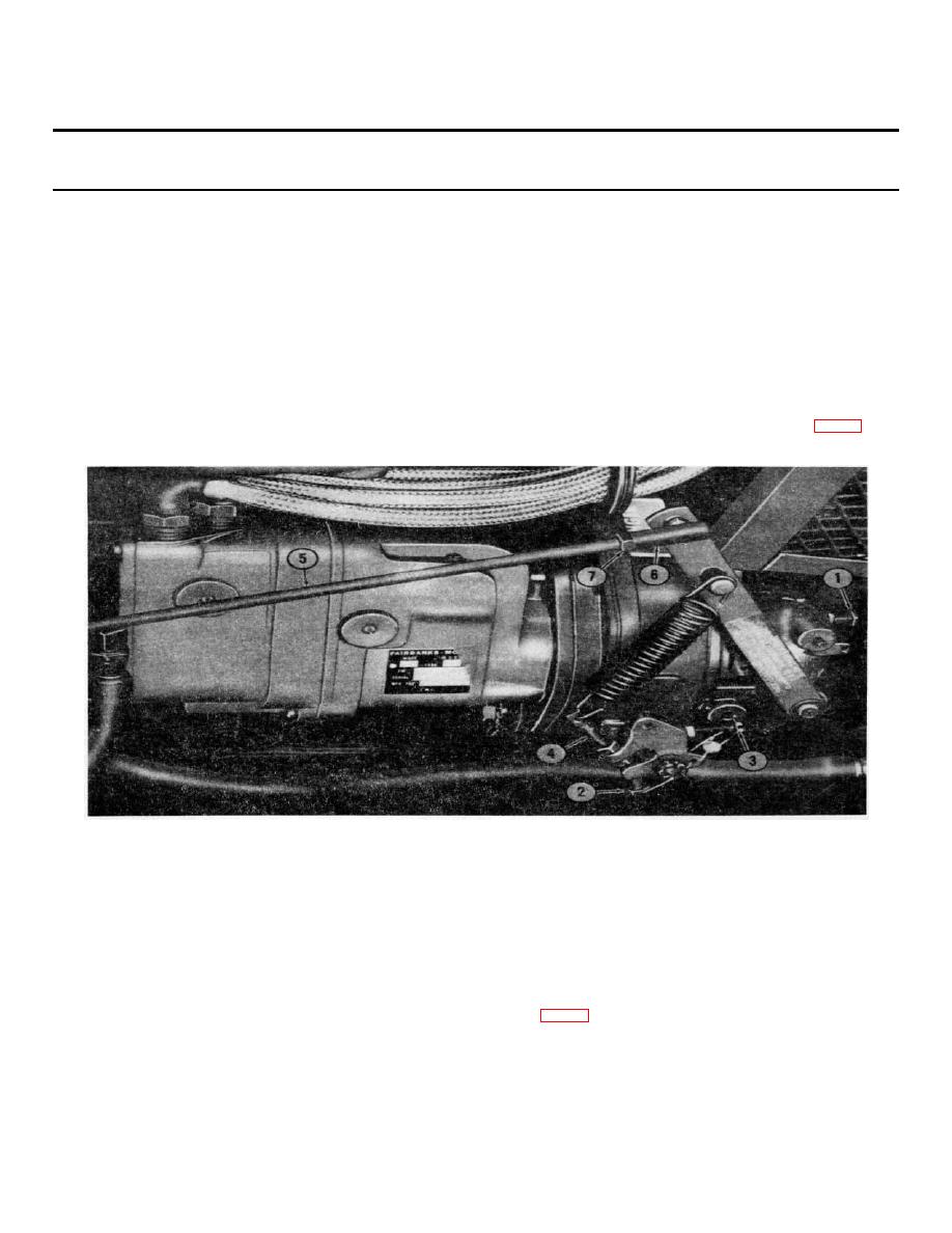
Figure 2-7. Governor adjustment. |
|
||
| ||||||||||
|
|
 TM 5-4320-234-34
Table 2-1. Troubleshooting - Continued
MALFUNCTION
TEST OR INSPECTION
CORRECTIVE ACTION
ENGINE CONTINUED
(2) To increase oil pressure, add a washer between spring and oil pressure regulator valve. More than four washers should not be
used. If four washers do not fulfill the required range, either the spring is faulty or other engine troubles exist.
(3) After you make the adjustments, check that the oil pressure remains In the required ranges during operation.
4. ENGINE LOCKS POWER, SMOKES, OR OPERATES ERRATICALLY
Step I. Check for incorrect engine timing
.
With the engine running at 600 rpm, use a timing light connected to the rear spark plug and check that the IGN-M indication on the fiywheel is alined
with the timing pointer.
If timing pointer and IGN-M indication on the flywheel are not aligned, the engine timing must be adjusted.
Loosen the magneto mounting hardware slightly and rotate the magneto slightly until the correct indication Is attained. Tighten the magneto
mounting hardware firmly.
6. ENGINE SPEED VARIES OR ENGINE SURGES
Check for a defective governor.
a. Start the engine and allow it to warm to operating temperature. While it is warming up, back out the surge adjusting screw (1, fig. 2-7) so that it
will not influence the governor setting.
1.
Surge adjusting screw
2.
Speed adjusting screw
8.
Speed adjusting lockscrew
4.
Sensitivity adjusting
5.
Throttle rod
6.
Nut
7.
Ball joint
Figure 2-7. Governor adjustment.
b. With the engine warme up and with the pump not under load adjust the engine idle speed to approximately 150 rpm higher than the required idle
d
speed under load. Make this adjustment by turning the adjusting screw (2, fig. 2-7). Back out speed adjusting lockscrew (3) so that it will not
influence the adjustment.
c. The governor's range of action is the differential between the engine speed under load and the engine speed without load. To broaden the range
of action use the sensitivity adjusting screw (4). Lengthen the Sensitivity adjusting screw to broaden the range of action of the engine. To
narrow the range of action, shorten the sensitivity adjusting screw (4) and compensate for seed change with the speed adjusting screw (3).
2-10
|
|
Privacy Statement - Press Release - Copyright Information. - Contact Us |
