 |
|||
|
|
|||
|
Page Title:
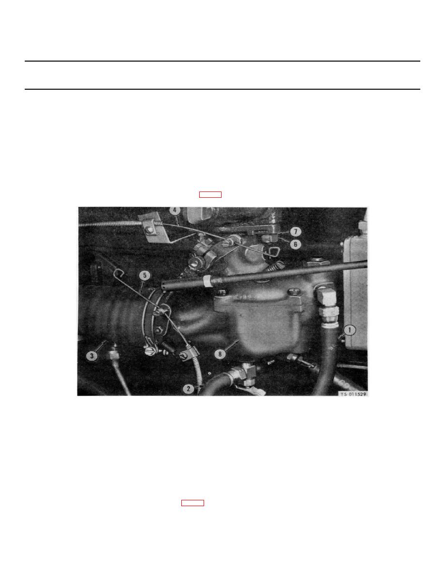
Figure 2-8. Carburetor removal. |
|
||
| ||||||||||
|
|
 TM 5-4320-234-34
Table 2-1. Troubleshooting - Continued
MALFUNCTION
TEST OR INSPECTION
CORRECTIVE ACTION
ENGINE CONTINUED
d. When the governor range of action is properly adjusted, allow the engine to run at governed seed, no load, and check for surging. If surging is
noted, turn in the surge adjusting screw (1) just far enough to eliminate the surging.
e. The surge adjustment can also be made by using the tachometer. With the engine running at governed speed, no load, turn in the surge
adjusting screw (1) until the engine speed increases 10 to 20 rpm and tighten the lock nut. If the carburetor and linkage are properly adjusted,
surge will disappear
f. If the governor cannot operate the throttle lever on the carburetor through the full operator range, it will be necessary to adjust the length of the
throttle rod (5) by loosening the nut (6) and adjusting the position of the ball joint (7).
g. When the governor adjustment is completed, tighten the speed adjusting lockscrew (2) to lock the cam in position. Make sure all locking nuts
are tightened.
If the governor cannot be adjusted, replace it.
(1) Disconnect the ball joint on governor to carburetor control rod from the lever on the governor.
(2) Disconnect fuel hoses (1 and 2, fig. 2-8) from the carburetor. Removeir cleaner hose (3) from the carburetor.
a
1.
Fuel hose
2.
Fuel hose
3.
Air cleaner hose
4.
Throttle control cable
5.
Choke control
6.
Nut
7.
Lockwasher
8.
Carburetor
Figure 2-8. Carburetor removal.
(3) Disconnect the ends of the throttle control cable (4) and choke control (5) from their respective levers on the carburetor.
(4) Remove nuts (6), lockwashers (7), and remove carburetor (8).
(5) Remove four screws (1, fig. 2-9) and lockwashers (2) that secure the cover (3) on the magneto; remove the cover and
gasket (4).
2-11
|
|
Privacy Statement - Press Release - Copyright Information. - Contact Us |
