 |
|||
|
|
|||
|
|
|||
| ||||||||||
|
|
 prevent shorts which could damage the
exist across the main terminals. Replace the unit if it
alternator, voltage regulator, and other parts.
fails to operate as indicated.
c. Installation. Installation of the reverse polarity
protector is the reverse of removal. Refer to items 20
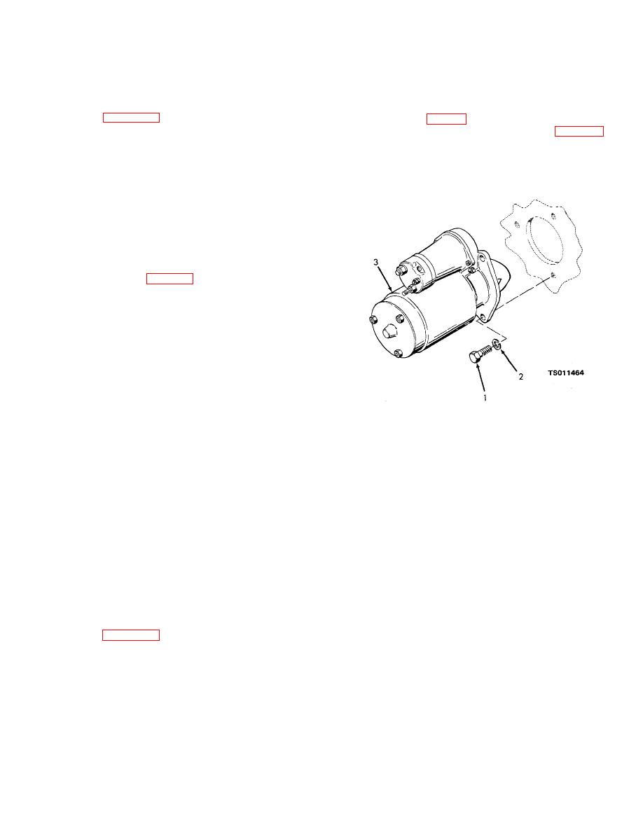
(1) Disconnect the electrical leads to the starter
through 23 in figure 4-25. If necessary, refer to figure 1-
solenoid switch (6, fig. 3-3).
4 for connection requirements.
(2) Remove the three cap screws (1, fig. 4-26)
4-41. Excitation Resistor
and lock washers (2) that secure the starting- motor (3)
a. Removal.
to the engine side of the flywheel housing; pull straight
CAUTION
forward on the starting motor to remove the assembled
Disconnect the battery cable from the
starter solenoid switch and starting motor from the
positive
battery
terminal
before
engine.
disconnecting any other leads from the
engine components.
This will prevent
shorts which could damage the alternator,
voltage regulator, and other parts.
(1) Disconnect the electrical leads from the
excitation resistor (27, fig. 4-25). Tag leads to facilitate
reassembly.
(2) Remove the cap screw (24), nut (25), and
lock washer (26) that secure the excitation resistor (27)
to the mounting bracket (30). Remove the cap screws
(28) and lock washers (29), and remove the bracket
(30) and spacer (31).
b. Cleaning and Inspection.
WARNING
Clean all parts in a well-ventilated area.
Avoid inhalation of solvent fumes and
prolonged exposure of skin to cleaning
solvent. Wash exposed skin thoroughly. Dry
1. Cap screw
cleaning solvent (fed. spec. P-D-680) used
2. Lock washer
to clean parts is potentially dangerous to
3. Starting motor
personnel and property. Do not use near
Figure 4-26. Starting motor mounting, exploded view.
open flame or excessive heat. Flash point of
solvent is 100 o to 138 F (38 to 59 C).
b. Cleaning and Inspection.
1) Clean the excitation resistor with a cloth
WARNING
dampened with dry cleaning solvent (fed. spec. P-
Clean all parts in a well-ventilated area.
D-680); dry thoroughly.
Avoid inhalation of solvent fumes and
(2) Inspect the excitation resistor for cracks,
prolonged exposure of skin to cleaning
signs of overheating, loose or damaged terminals, and
solvent. Wash exposed skin thoroughly. Dry
other damage.
Use a multimeter to check the
cleaning solvent (fed. spec. P-D-680) used
resistance of the unit. Resistance must be 33 ohms.
to clean parts is potentially dangerous to
Replace the resistor if it is damaged or if resistance is
personnel and property. Do not use near
incorrect.
open flame or excessive heat. Flash point of
c. Installation. Installation of the excitation
solvent is 100 O to 138 O F (38 to 59 C).
resistor is the reverse of removal. Refer to items 24
through 31 in figure 4-25. If necessary, refer to figure 1-
(1) Clean the exterior of the starting motor with
4 for connection requirements.
a cloth dampened with dry cleaning solvent (fed. spec.
4-42. Engine Starting Motor
P-D-680). Take care to prevent solvent from entering
a. Removal.
the starting motor.
(2) Inspect the starting motor for cracks, signs
CAUTION
of overheating, loose solenoid switch mounting,
Disconnect the battery cables from the
damaged pinion teeth on the drive, and other damage.
positive
battery
terminals
before
disconnecting any other electrical leads
from the engine components.
This will
4-44
|
|
Privacy Statement - Press Release - Copyright Information. - Contact Us |
