 |
|||
|
|
|||
|
Page Title:
Figure 3-3. Left side of engine showing components. |
|
||
| ||||||||||
|
|
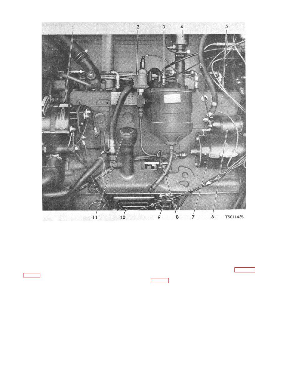 1.
5.
Water temperature sender
9. Reverse polarity protector
2.
Oil pressure sender
6.
Starter solenoid switch
10. Voltage regulator
3.
Oil filter
7.
Engine starting motor
11. Engine oil filler cap
4.
Engine overspeed governor
8.
Oil level dipstick
Figure 3-3. Left side of engine showing components.
(5) Check the oil level on the oil level dipstick
(1) Drain oil and replace plugs (para 3-3a).
(8, fig. 3-3). Oil must be up to the full mark. Add oil if
(2) Remove the screw in the oil filter cover (1,
necessary, but do not overfill.
b. Every third oil change (150 operation hours
maximum), replace the oil filter as follows:
3-5
|
|
Privacy Statement - Press Release - Copyright Information. - Contact Us |
