|
| |
TM 9-2330-398-24
3-34. 4-INCH PUMP ASSEMBLY REPAIR ((continued).
5.
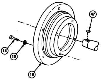
Remove six screws (14), lockwashers (15) from
pump coupling (16). Discard lockwashers.
NOTE
Number of shims may vary.
NOTE
If Installing same pump, use same shims, mark the location and number of the
shims used in the mounting of the pump.
6.
Remove two screws (17), washers (18), and shims (19).
WARNING
To avoid personnel injury, use a hoist or get assistance when lifting components
that weigh more then 50 Ia.
7.
Remove pump assembly (20).
b. DISASSEMBLY
1.
Remove eight nuts (21), lockwashers (22), Intermediate housing (35), seal plate (34), impeller (29) and gasket
(30) from volute (26) as an assembly.Discard gasket.
WARNING
The spring load on the mechanical seal may cause the impeller to fly off the shaft it
is being removed, causing serious injury to personnel
2.
Unscrew Impeller (29) from Impeller shaft (41). Unscrew the impeller in the same direction as the pump turns.
3.
Remove seal plate (34), mechanical seal (33), spring seat (32), and shims (31) from impeller shaft.
4.
Remove four screws (46), lockwashers (22), bearing cap (44), and gasket (43). Discard gasket.
5.
Remove pump coupling (16) and key (47) from impeller shaft.
3-104
|

