Order this information in Print

Order this information on CD-ROM

Download in PDF Format


Click here to make tpub.com your Home Page

Page Title: INSTALLATION
Back | Up | Next

Click here for a printable version

Google


Web
www.tpub.com

Home


Information Categories
.... Administration
Advancement
Aerographer
Automotive
Aviation
Combat
Construction
Diving
Draftsman
Engineering
Electronics
Food and Cooking
Math
Medical
Music
Nuclear Fundamentals
Photography
Religion
USMC
   
Products
  Educational CD-ROM's
Printed Manuals
Downloadable Books


TM 9-2330-398-24 3-24. GOVERNOR UNKAGE ASSEMBLY REPAIR (continued). 2. Start engine (refer to TM 9-2330-398-10) and run at 1200 rpm. NOTE Step 3 is for coarse adjustment of governor linkage; step 4 is for fine adjustment.
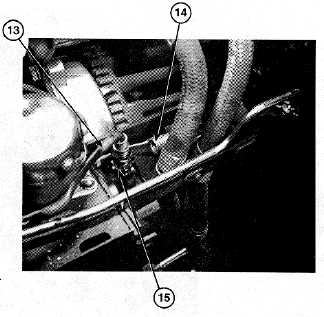
 3. Relocate spring (14) in notches in governor arm (13) to eliminate rough idling or loping of engine. 4. Turn ratchet hub (15) clockwise to decrease rpm, counterclockwise to increase rpm to eliminate rough idling. 5. Stop engine (refer to TM 9-2330- 3 10).
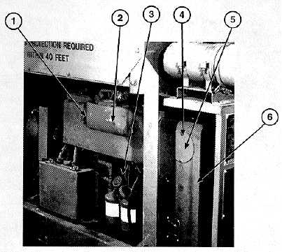
 6. Replace engine door panel (2) on engine assembly (3), and tighten two retainer screws (1). 7. Install access cover (5) and screw (4) on engine blower housing (6). FOLLOW-ON MAINTENANCE: Disconnect ground (refer to TM 9-2330-398-10). 3-76

Privacy Statement - Press Release - Copyright Information. - Contact Us - Support Integrated Publishing

Integrated Publishing, Inc. - A (SDVOSB) Service Disabled Veteran Owned Small Business