|
| |
TM 9-2330-398-24
3-10. BOGIE ASSEMBLY REPLACEMENT (continued
4.
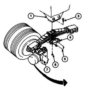
Position two jacks at each end of trunnion tube (5) as close as possible to inside of each trunnion hanger (4).
5.
Using lifting device, raise semitrailer to within one inch (2.54 cm) of trunnion hangers (4).
6.
Using lifting device, lower semitrailer off supports or cribbing. Remove supports or cribbing.
7.
Align holes in mounting brackets (1) with holes in trunnion hangers (4).
8.
Loosely install eight screws (3) and new self-locking nuts (6) in mounting brackets (1) and trunnion hangers (4)
9.
Raise jacks until mounting brackets (1) are seated against trunnion hangers (4).
10.
Torque eight self-locking nuts (6) to 90 Ib-ft (122 Nom). Lower and remove jacks.
11.
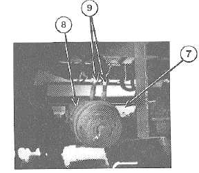
Connect eight hoses (9) to four brake air chambers (8) on two axles (7) as tagged.
FOLLOW-ON MAINTENANCE:
•· Uncage fail-safe chamber brakes (para 2-60).
• Disconnect ground (refer to TM 9-2330-398-10).
3-34
|