|
| |
TM 9-2330-398-24
2-50. SLACK ADJUSTER REPLACEMENT.
This Task Covers:
a. Removal
b. Cleaning and Inspection
c. Installation
d. Adjustment
Initial Setup:
Tools and Test Equipment:
Equipment Conditions:
• Common no. 1 tool set (Item 1, Appendix B)
• Semitrailer uncoupled (refer to TM 9-2330-398-10).
• General mechanic's tool kit (Item 4, Appendix B)
• Semitrailer bonded and grounded (refer to
TM 92330-398-10).
Material/Parts:
• Air reservoirs drained (refer to TM 9-2330-398-10).
• Rag (Item 25, Appendix C)
a Fail-safe chamber brakes caged (para 2-60).
• Cotter pin (Item 7, Appendix F)
• Cotter pin (Item 10, Appendix F)
• Retaining ring (Item 146, Appendix F)
a. REMOVAL
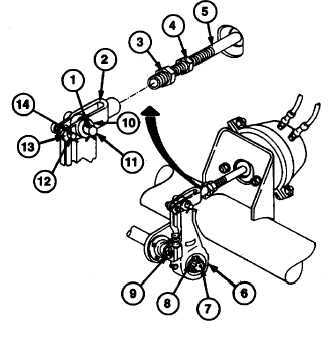
1. Loosen brake actuator push-rod jamnut (4). Loosen yoke adapter (3) until it is free of yoke (2).
NOTE
A lot more torque is required to rotate slack adjuster manual adjustment hex
counterclockwise than is necessary to rotate it clockwise. Torque may be as high
as 70 Ib-ft (94.9 N m).
2. Rotate slack adjuster manual adjustment hex (9)
counterclockwise until slack adjuster (6) is clear
of brake actuator push rod (5).
3. Remove retaining ring (8) from recess on end of
camshaft (7). Discard retaining ring.
4. Using soft-faced hammer, tap on slack adjuster
(6) lightly until it can be removed from camshaft
(7).
5. Remove two cotter pins (1 and 14), yoke pin
(11), link pin (12), two washers (10 and 13), and
yoke (2) from slack adjuster (6). Discard cotter
pins.
2-128
|

