|
| |
TM 9-2330-398-24
2-49. BRAKESHOE REPLACEMENT (continued).
6.
Tighten nut (22) and bolt (20) between 100 and
120 Ib-ft (135.6 and 162.7 N m).
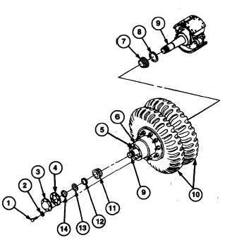
7.
Install inner wheel bearing (7) and new seal (8)
in hub and drum assembly (6).
8.
Place wheel lift jack under tires (10), and slide
tires (10), wheels, and hub and drum assembly
(6) onto spindle (9).
9.
Install outer wheel bearing (11) on spindle (9).
10.
Install inner wheel bearing nut (12) on spindle (9)
and tighten to a minimum of 75 ft-lb (102 Nom)
to ensure proper seating of wheel bearings (7
and 11). Loosen inner wheel bearing nut (12)so
wheel will turn freely.
11.
To properly position bearing for final adjustment,
tighten inner wheel bearing nut (12) to 50 ft-lb
(69 Nom) while rotating wheel.
12.
Loosen inner wheel bearing nut (12) 1/3 turn.
13.
Install lockring (13) on spindle (9) so dowel on
inner wheel bearing nut (12) aligns with hole in
lockring (13) and tang fits in keyway of spindle
(9).
WARNING
Failure to torque outer wheel bearing nut properly can cause wheel to come off
during vehicle ol3ratlon, which could result In Injury or death to personnel or
damage to equipment
14.
Install outer wheel bearing nut (14) on spindle (9). Tighten outer wheel bearing nut (14) between 250 and 400 ft-lb
(339 and 542 N m).
15.
Apply light coat of grease to new gasket (4) and position gasket (4) on hub and drum assembly (6).
16.
Install hubcap (3) on hub and drum assembly (6) with six bolts (1) and new lockwashers (2). Tighten bolts
between 16 and 20 ft-lb (22 and 27 N m).
FOLLOW-ON MAINTENANCE:
• Uncage fail-safe chamber brakes (para 2-60).
• Install wheel (if necessary) (para 2-62 or 2-63).
• Disconnect ground (refer to TM 9-2330-398-10).
2-127
|