|
| |
TM 9-2330-272-14
4-81. AUXILIARY ENGINE INSTRUMENT PANEL HARNESS ASSEMBLY AND CIRCUIT
BREAKER REPLACEMENT (Con’t).
4.
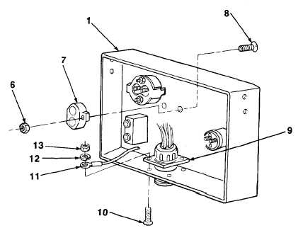
Disconnect plug connectors from switches, gages, and circuit breaker (7) (para 4-80).
5.
Remove four nuts (13), Iockwashers (12), screws (10), ground lead (11), and harness assembly (9) from
instrument panel (1). Discard lockwashers.
6.
Remove two nuts (6), screws (8), and circuit breaker (7) from instrument panel (1).
1.
Install circuit breaker (7) on instrument panel (1) with two screws (8) and nuts (6).
2.
Install harness assembly (9) and ground lead (11) on instrument panel (1) with four screws (10), new
Iockwashers (12), and nuts (13).
3 .
Connect plug connectors to switches, gages, and circuit breaker (7) (para 4-80).
4.
Install instrument panel (1) in cabinet with four screws (3) and nuts (2).
5.
Connect cable (5) to receptacle (4).
FOLLOW-ON TASKS:
Connect battery cables (para 4-25).
TA702803
4-173
|