Order this information in Print

Order this information on CD-ROM

Download in PDF Format


Click here to make tpub.com your Home Page

Page Title: AUXILIARY ENGINE INSTRUMENT PANEL HARNESS ASSEMBLY AND CIRCUIT BREAKER REPLACEMENT.
Back | Up | Next

Click here for a printable version

Google


Web
www.tpub.com

Home


Information Categories
.... Administration
Advancement
Aerographer
Automotive
Aviation
Combat
Construction
Diving
Draftsman
Engineering
Electronics
Food and Cooking
Math
Medical
Music
Nuclear Fundamentals
Photography
Religion
USMC
   
Products
  Educational CD-ROM's
Printed Manuals
Downloadable Books


TM  9-2330-272-14 4-81.  AUXILIARY  ENGINE  INSTRUMENT  PANEL  HARNESS  ASSEMBLY  AND  CIRCUIT BREAKER   REPLACEMENT. This Task Covers: a. Removal b. Installation Initial  Setup: Equipment   Conditions: Materials/Parts: Battery  cables  disconnected  (para  4-25). Marker tags (Item 17, Appendix E) TooIs/Test  Equipment: Four  Iockwashers General mechanic’s tool kit N O T E Auxiliary engine instrument panel harness and circuit breaker are replaced the same way on all models except quantity of plug connectors may vary. M131A5 is illustrated.
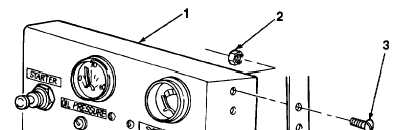
 1. Disconnect cable (5) from receptacle (4). 2. Remove four nuts (2), screws (3), and instrument panel (1) from cabinet. 3. Tag wires for installation if identification bands are missing or not legible (para 4-20). TA702802 4-172

Privacy Statement - Press Release - Copyright Information. - Contact Us - Support Integrated Publishing

Integrated Publishing, Inc. - A (SDVOSB) Service Disabled Veteran Owned Small Business