|
| |
TM 55-2915-335-30&P
Table 2-1. Fault Isolation - Continued
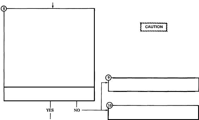
From block 6
l
Check pump for maximum flow rate.
NOTE
After installing pump in test tank, DO NOT per-
form test procedures detailed in paragraph 2-
25. Test pump as follows:
l
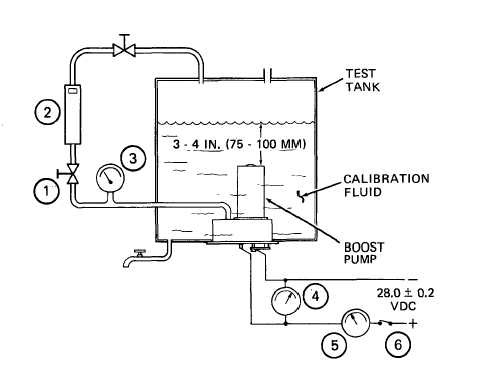
Install pump or cartridge in test tank per
final test procedure (paragraph 2-25). Set
up for pressure and flow check as in-
structed.
l
Turn power ON.
l
Adjust voltage to 28 VDC.
l
Open flow control valve (1).
l
Observe fuel flow at flowmeter (2).
Does pump reach 1000 PPH (454 kg/hr) flow
rate?
LEGEND
1. FLOW CONTROL VALVE
2. FLOWMETER
3. PRESSURE GAGE
4. VOLTMETER
5. AMMETER
6. POWER ON/OFF SWITCH
After completing fault isolation, and before
proceeding to the malfunction test or in-
spection, the following is required: Close
flow control valve, adjust voltage to 0 VDC,
turn power OFF and if necessary remove
complete pump assembly or pump cartridge
from test tank per paragraph 2-25, step 6.
If pressure reads 0 PPH (0 kg/hr), proceed to
Malfunction Number 3 of Table 2-2.
If pressure reads more than 0 PPH (0 kg/hr),
proceed to Malfunction Number 4 of Table 2-2.
To block 11
2-4
|