|
| |
TM 5-5430-218-13
1-7.
LOCATION AND DESCRIPTION OF MAJOR COMPONENTS - (Continued).
c .
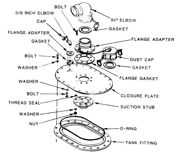
Filler/Discharge Assembly
( S e e F i g u r e 1 - 3 ) .
T h e f i l l e r / d i s c h a r g e a s -
sembly consists of a ninety degree (90°)
elbow, a flange adapter, a clo-
sure plate and a suction stub.
A reducer and a four-foot section of 3
inch hose connects the 3 inch gate valve with the filler/discharge as-
sembly.
Filling and discharge operations can be made by connecting addi-
tional hoses to the unused connection on the gate valve.
Dust caps and
dust plugs are provided to protect unused connections.
Figure 1-3.
Filler/Discharge Assembly
1-4
|

