|
| |
TM 5-5430-218-13
b.
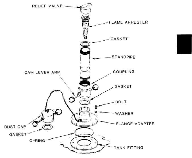
Vent and Pipe Assembly
(See Figure 1-2) .
The vent and pipe assembly is
attached to the top center of the tank envelope using a 2 inch quick-
disconnect coupling.
The assembly uses a relief valve to vent air and
fuel vapor during filling operations.
The assembly also removes vapors
during normal fuel storage and prevents air from entering the tank. The
a b s e n c e o f a i r c a u s e s t h e t a n k t o c o l l a p s e a s f u e l i s d i s p e n s e d or
drained.
Figure 1-2.
Vent and Pipe Assembly
1-3
|