|
| |
TM5-4930-235-13&P
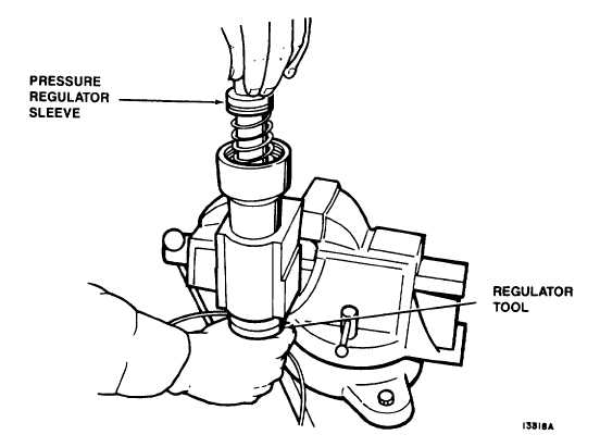
Figure 5-8. Regulator Sleeve Installation
(f) Let pullback sleeve (27) slide up and over release pins (29) until end of pullback sleeve (27) is close
to hole in release pins (29).
(g) Install one ball bearing (30) in each hole. Let pullback sleeve (27) slide up and touch ball bearings
(30).
(h) Push down on release pins (29) while carefully holding pullback sleeve (27) to prevent rapid upward
movement. Pullback sleeve (4) will slide down slightly, then slide up to hold release pins (29) and
ball bearings (30) in place.
CAUTION
Do not use an extension or cheater bar with spanner wrench. Failure to comply can result in
damage to parts.
(i) Thread latch adapter (33) into nozzle body (47) and tighten using spanner wrench.
(14) Remove regulator tool as follows:
(a) Pull down on handle and remove cotter pin.
(b) Remove front plate.
(c) Pull regulator tool out through bottom of nozzle body (47).
5-17
|

