Order this information in Print

Order this information on CD-ROM

Download in PDF Format


Click here to make tpub.com your Home Page

Page Title: Figure 5-17. Piston and Rack Assembly
Back | Up | Next

Click here for a printable version

Google


Web
www.tpub.com

Home


Information Categories
.... Administration
Advancement
Aerographer
Automotive
Aviation
Combat
Construction
Diving
Draftsman
Engineering
Electronics
Food and Cooking
Math
Medical
Music
Nuclear Fundamentals
Photography
Religion
USMC
   
Products
  Educational CD-ROM's
Printed Manuals
Downloadable Books


TM 5-4930-234-13&P (e) 
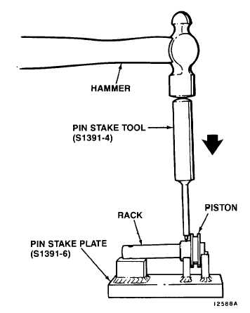
Check spring pin (13).  It must be flush on both sides of piston (14). 
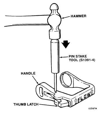
23.  If required, assemble thumb latch (26) to handle (22) as follows.  See Figure 5-18. (a) Place handle (22) on a flat surface. (b) Insert thumb latch (26) in side of handle (22) and align holes. (c) Insert  spring  pin  (25)  in  handle  (22).    Drive  spring  pin  (25)  through  handle  (22)  and  thumb  latch  (26) using pin stake tool, S1391-4, and hammer. (d) Remove pin stake tool.  Check spring pin (25).  It must be flush with surface of handle (22). (e) Pivot thumb latch (26) away from handle (22).  Install latch spring (27’ in thumb  latch  (26)  and  hole  in handle (22). Figure 5-17.  Piston and Rack Assembly Figure 5-18.  Handle and Thumb Latch Assembly 5-23

Privacy Statement - Press Release - Copyright Information. - Contact Us - Support Integrated Publishing

Integrated Publishing, Inc. - A (SDVOSB) Service Disabled Veteran Owned Small Business