|
| |
TM 5-4930-234-13&P
20.
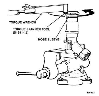
Tighten nose sleeve (38) to a torque of 20-30 ft-lbs using torque spanner tool, S1391-12, and a torque
wrench. See Figure 5-16.
21.
Remove body (49), from vise. Remove vise jaws, S1391-15, from body (49). Install body (49) in vise
with nose sleeve (38) pointing down.
22.
If required, assemble piston (14) to rack (10) as follows. See Figure 5-17.
(a)
Slide rack (10) into piston (14) and align pin hole.
(b)
Place rack (10) and piston (14) in pin stake plate, S1391-6.
(c)
Insert spring pin (13) in hole of piston (14). Drive spring pin (13) into position using pin stake tool,
S1391-4, and hammer.
(d)
Remove pin stake tool. Remove rack (10) and piston (14) from pin stake plate.
Figure 5-15. Adapter Installation
Figure 5-16. Torqueing Nose Sleeve
5-22
|