|
| |
TM 5-4320-313-14
CAUTION
The valve recession must not be less than 0.018 inch (0.45 mm), otherwise valve head may touch
piston.
(9) The valve recession shall be a maximum of 0.0275 inch (0.70 mm) and a minimum of 0.0180 inch (0.45
mm).
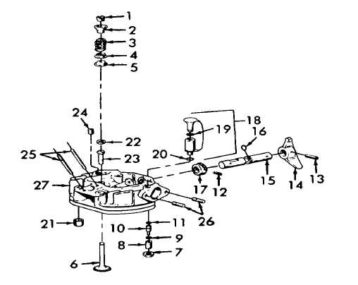
e. Reassembly. (Refer to figure 6-3).
(1) Install two studs (26 and 25) into cylinder head (27).
(2) Install closing screw (24).
(3) Press in two valve guides (23) and install two spacer rings (22), if removed.
(4) Install two pins (21). Install new packing (20), new packing (19), and oil fill device (18).
(5) Install pinion (17), new packing (16), shaft (15), lever (14), and pins (13 and 12).
NOTE
• Plates (9) have a bevel side and a smooth side. Install plates (9) in pairs, bevel side to bevel side.
• Lever (14) must be in the run position before installing threaded pin (8).
Figure 6-3. Cylinder Head Reassembly.
6-5
|