|
| |
TM 5-4320-306-24
4-12.
REPLACE/REPAIR CRANKSHAFT ASSEMBLY (Continued)
4
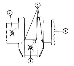
Visually inspect crankshaft journals and crankpins for overheating, cracking, excessive wear, or other damage.
Visually inspect for cracks which start at a crankpin or journal oil hole (1 or 2) and follow the journal or crankpin
surface at an angle of 45 degrees to the axis. Inspect for cracks in critical fillet areas (3). Replace crankshaft (4)
if cracks are visible Inspect for minute cracks using MlL-l-6868 Magnetic Particle Inspection. Replace crankshaft
if any cracks are found or if it has been overheated.
5
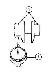
Check alinement at adjacent center and main bearing journals (1) with a dial indicator (2) Maximum allowable
runout is 0.002 inch (0.0508 mm). Replace crankshaft, if necessary.
6
Inspect crankpins.
a.
Measure diameter of each crankpin (1) at points 1 and 2 and along axes A and B with micrometer.
Measure width of crankpin at point 3. Measure radius of fillets (2) between crankpin and crank cheek (3).
b
Diameter should be 2.5185 to 2.5193 inches (63.971 to 63.99 mm) If any measurement is outside the
specified limits, crankshaft must be replaced
4-96
|