|
| |
TM 5-4320-306-24
4-11.
REPLACE/REPAIR CONNECTING ROD ASSEMBLY (Continued)
15
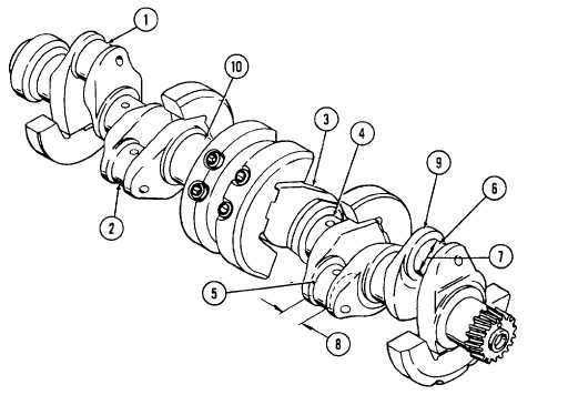
Measure diameter and width of all six crankpins (1 through 6) and record measurements. Make sure
measurements are identified as cylinder No. 1, cylinder No. 2, and so on. Cylinder No. 1 is closest to the
flywheel end of the engine; cylinder No. 6 is closest to the blower end.
NOTE
When determining bearing shell radial and side clearance, make sure connecting rods and bearing shells
are properly matched and also properly matched to the corresponding crankpin.
16
Check bearing shell radial clearance.
a
Take the smallest measurement of the bearing shell bore that is still within the tolerance limits, measured
in step 14, and subtract largest crankpin diameter (7) measurement measured in step 15. The difference
between these two measurements is the bearing shell radial clearance. It should be 0.0016 to 0.0039 inch
(0.04 to 0.099 mm) under normal conditions.
b.
Radial clearance upper limit value is 0.0118 inch (0.3 mm). If radial clearance is less than 0.0016 inch
(0.04 mm), replace bearing shells.
17
Check bearing shell side clearance.
a.
Measure crankpin width (8) and record the measurement. Subtract connecting rod width measured in step
10. The difference is bearing shell side clearance and it should be 0.0189 to 0.0229 inch (0.48 to 0.582
mm) under normal conditions.
b.
The side clearance upper limit value is 0.0315 inch (0.8 mm). If the side clearance is less than 0.0189
inch (0.48 mm), the connecting rod should be rechecked and remeasured. Replace the connecting rod if
necessary.
4-88
|