|
| |
TM 5-4320-306-24
3-11. REPLACE/REPAIR OIL PUMP ASSEMBLY (Continued)
ASSEMBLY
1
Using bolt (20), nut (21), and toothed washer (22), secure pipe clips (3) to suction pipe (5). Tighten the nut and
bolt only tight enough to hold the clips on the pipe.
2
If either hydraulic pipe (14) or yoke spring (13) have been replaced, assemble the spring and pipe by sliding the
pipe into the clamping portion of the spring.
3
Place a new preformed packing (23) on the end of hydraulic pipe (14) and slide the long end of the pipe into the
outlet (upper, unthreaded) port of the pump. Be sure the preformed packing seats properly to provide a seal.
INSTALLATION:
1
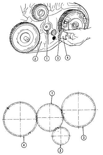
Insert bushing (1) into crankcase
(2).
2
Install journal
(3)
into crankcase
bore. Be sure to aline bushing hole
(4)
in the journal with the bushing.
3
Check the reference marks on idler
gear (1), crankshaft gear (2), cam-
shaft gear (3), and injection pump
gear (4).
4
Aline the idler gear marks with those
of the crankshaft, camshaft, and in-
jection pump gears, as noted during
disassembly.
5
Place the idler gear on the journal.
The teeth of the other gears may
hold the idler gear and journal in
place. If they do not, hold the idler
gear in place by hand until the yoke
spring can be installed to secure the
idler gear.
3-56
|

