|
| |
TM 5-4320-305-24
4-12. REPLACE/REPAIR CRANKSHAFT ASSEMBLY (Continued)
3
Passing 3/4 inch (19.05 mm) rope or fabric lifting slings through cylinder bores 1 and 6, secure the crankshaft so it
will not fall from the crankcase when the bearing caps are removed.
4
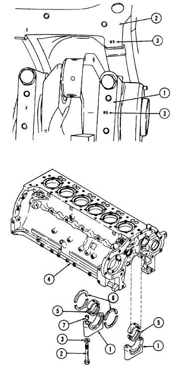
Check that each bearing cap (1) is marked with a
corresponding matchmark on the crankcase (2). The
matchmarks must indicate direction of match as well
as location.
5
If there are no existing matchmarks, mark each
bearing cap (1) and its corresponding position with an
identification number (3). The number and direction
of the number should be the same for each cap and
crankcase position.
6
Starting with the front and rear bearing caps (1), and
working toward the center bearing caps, remove the
bolts (2) and washers (3)' that secure each bearing
cap to the crankcase (4).
7
Remove bearing caps (1), main bearings (5), and
stop rings (6). Be sure to note location of the two
stop rings to aid in installation. Remove dowel
bushings (7) that aline each bearing cap to
crankcase.
8
Follow procedure described in paragraph 4-13 for
inspection, repair, or replacement of bearing cap,
bracket, and main bearing.
9
Release the slings holding the crankshaft in position
and remove it from the crankcase.
4-94
|

