|
| |
TM 5-4320-305-24
4-11. REPLACE/REPAIR CONNECTING ROD ASSEMBLY (Continued)
c.
Remeasure bearing shell bore in accordance with step 14. The bearing shell bore, for example, should be
2.5209 to 2.5224 inches (64.03 to 64.069 mm). However, if the bore measures an additional 0.0008 inch
(0.020 mm) on either side of tolerance limits, the connecting rod and bearing shells would still be acceptable
for reinstallation. The tolerance limits would then become 2.5217 to 2.5232 inches (64.05 to 64.089 mm) and
the connecting rod and bearing shells would be acceptable for further use.
d.
If bearing shell bore measurements are still outside the extended tolerance limits, the connecting rod must be
replaced. This would include replacement of small-end bushing, bearing shells, bearing cap, dowel pin, and
big-end bolts.
INSTALLATION:
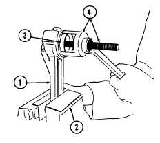
1
If connecting rod (1) has been replaced, clamp new
connecting rod into padded vise (2) and pull in small-end
bushing (3) with piston pin bush inserter No. 131310 (4).
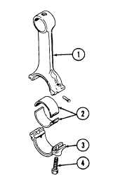
2
If connecting rod (1) and/or bearing shells (2) have been replaced,
matchmark connecting rod, bearing shells, and bearing cap (3) for
each cylinder. Always use new big-end bolts (4) for installation of
connecting rod and bearing shells onto crankpin on crankshaft.
Tighten bolts (2) to 22.13 ft-lb (30 N.m) torque. Using a torque
gage, retighten bolts an additional 60 degrees, then an additional
30 degrees.
4-91
|