Order this information in Print

Order this information on CD-ROM

Download in PDF Format


Click here to make tpub.com your Home Page

Page Title: REPLACE/REPAIR CONNECTING ROD ASSEMBLY (Continued)
Back | Up | Next

Click here for a printable version

Google


Web
www.tpub.com

Home


Information Categories
.... Administration
Advancement
Aerographer
Automotive
Aviation
Combat
Construction
Diving
Draftsman
Engineering
Electronics
Food and Cooking
Math
Medical
Music
Nuclear Fundamentals
Photography
Religion
USMC
   
Products
  Educational CD-ROM's
Printed Manuals
Downloadable Books


TM 5-4320-305-24 4-11. REPLACE/REPAIR CONNECTING ROD ASSEMBLY (Continued) 7 Measure connecting rod bore (1) with inside micrometer.  Bore (1) should measure 1.6929 to 1.6935 inches (43.0 to 43.015 mm).  If measurement is outside specified limits, replace connecting rod. 8 
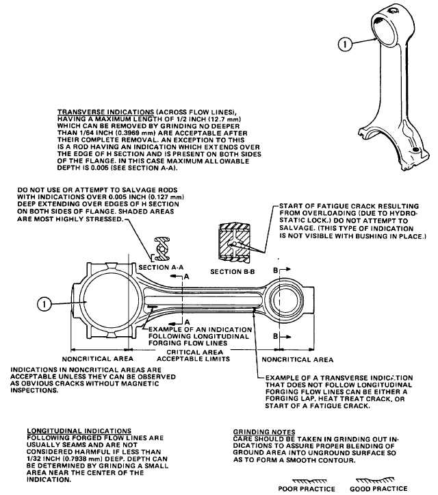
Visually inspect connecting rod for bending, warping, cracking, rust, or other damage.  Check for cracks using MIL- 1-6868  magnetic  particle  inspection.    Replace  if  twisted  or  bent.    Grind  or  replace  if  indications  of  cracks  are revealed  by  magnetic  particle  inspection.    Stamp  the  cylinder  number  on  a  replacement  connecting  rod  and bearing cap. 4-85

Privacy Statement - Press Release - Copyright Information. - Contact Us - Support Integrated Publishing

Integrated Publishing, Inc. - A (SDVOSB) Service Disabled Veteran Owned Small Business