|
| |
TM 5-4320-305-24
4-11. REPLACE/REPAIR CONNECTING ROD ASSEMBLY (Continued)
4
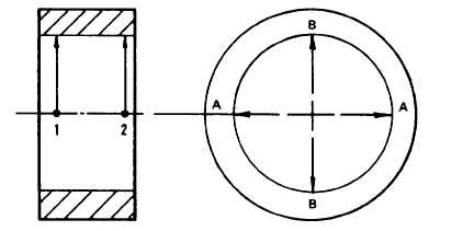
Inspect small-end bushing.
a.
Adjust inside micrometer to 1.5748 inches (40.0 mm).
b.
Measure and record small-end bushing bore or inside diameter. Measure at points 1 and 2 along axes A and
B. Measurements should be 1.5763 to 1.5781 inches (40.038 to 40.084 mm). If any measurement is outside
these limits, replace small-end bushing.
c.
Inspect for scoring, overheating, or other damage. Replace as necessary. Measure outside diameter of
bushing with outside micrometer. Measurement should be 1.6949 to 1.6961 inches (43.05 to 43.08 mm). If
measurement is outside specified limits, replace small-end bushing.
5
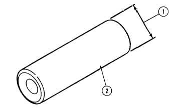
Measure and record diameter (1) of corresponding
piston pin (2) with micrometer at several points along
the length of the pin. The diameter should be 1.5746
to 1.5748 inches (39.995 to 40.0 mm). If
measurement is outside these limits, replace piston
pin.
6
Check piston pin clearance in small-end bushing.
a.
Subtract piston pin diameter measured in step 5 from small-end bushing bore measurement recorded in step
4. Clearance should be 0.0015 to 0.0035 inch (0.038 to 0.089 mm) under normal conditions.
b.
If clearance is greater than 0.0098 inch (0.25 mm), piston pin and small-end bushing should be remeasured
and clearance redetermined.
c.
If clearance is still greater than 0.0098 inch (0.25 mm), replace piston pin or small-end bushing, or both. Be
sure to recheck measurements and clearances to see that they fall within their respective tolerance limits.
4-84
|


