|
| |
TM 5-4320-305-24
3-19.
REPLACE CYLINDER HEAD ASSEMBLY, ROCKER ARMS, PUSHRODS, AND TAPPETS (Continued)
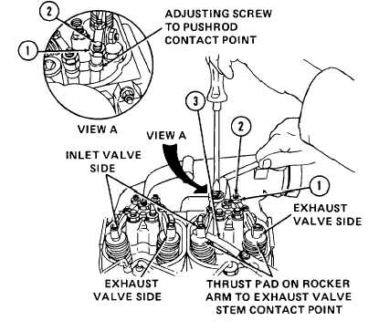
2
Loosen nuts (1) on adjusting
screws (2) on inlet and exhaust
valve rocker arms. Insert a
feeler gage (3) of 0.0059 inch
(0.15 mm) thickness between
valve stem and thrust pad of
each rocker arm. Turn slotted
adjusting screws (2) until they
are
in
contact
with
their
respective
pushrods
and
exerting
approximately
the
same contact pressure against
pushrods as thrust pads are
against the feeler gage and
valve stems. Retighten hex
nuts securely.
3
Rotate crankshaft in running direction several complete revolutions.
4
Recheck valve clearance. Make sure that feeler gage distance and contact pressures are the same as adjusted
previously in step 2 above.
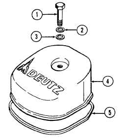
5
Install new gasket (5) with sealing compound. Install cover
(4), washers (2 and 3), and hex bolt (1). Tighten hex bolt to
20.65 ft-lb (28 N.m).
3-111
|