|
| |
TM 5-4320-305-24
3-11.
REPLACE/REPAIR OIL PUMP ASSEMBLY (Continued)
9
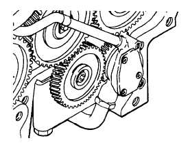
Oil pump gear-to-crankshaft gear backlash should be
0. 039 to 0.078 inch (1 to 2 mm). Adjust backlash by
sliding oil pump in toward crankcase to decrease
backlash. Increase backlash by sliding oil pump away
from crankcase. Tighten screws to 25 ft-lb (35 N-m).
10
Using bolts (1) and lockwashers (2), secure assembled pipe clips (3) and suction pipe (5) to the lower bearing cap.
11
Move suction pipe (5) in pipe clips (3) as required to install a new duplex ring (6) and the suction pipe end into the
intake (lower, threaded) port of oil pump (7).
12
Tighten cap screw/nut (4) to secure the suction pipe (5) and duplex ring (
6) in oil pump (7).
13
Make sure reference markings on idler, crankshaft, camshaft, and injection pump gears are alined properly. Secure
idler gear by tightening the screw (12) to 22.13 ft-lb (30 N.m) torque. Then tighten screw an additional 60 degrees.
14
Tighten bolts (1) and screws (8) to a torque of 25.81 ft-lb (35 N.m).
3-58
|