|
| |
TM 5-4320-305-24
2-45. REPLACE/REPAIR WHEEL BRAKES (Continued)
4
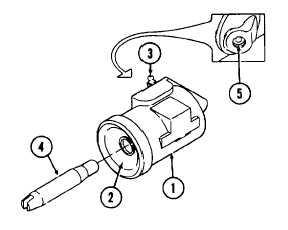
Inspect wheel cylinder assembly (1) for signs of
fluid leakage, broken boot (2), frozen or damaged
bleeder valve (3). Inspect push rod (4) for worn
groove or corrosion. Inspect tube seat (5) for
sharp
edges,
corrosion,
or
other
damage.
Replace entire assembly if damaged.
5
Inspect hub and drum for damaged threads on
studs. Inspect interior of drum for signs of uneven
wear or scoring. Replace if damaged. Remove
grease or oil from interior of drum.
6
Inspect hand brake, brake cables, crossmember
slide, J-bolt, and angle brackets for minor dents,
rust, corrosion, damage, or damaged threads.
Inspect for sticking or frozen hand brake.
Lubricate frozen or sticking hand brake with
lubricating
oil.
Replace
components
as
necessary.
7
Inspect hydraulic union, tee, hose clips, and mounting hardware for damage, rust, and corrosion. Inspect brake
hoses for cracking or brittleness. Replace damaged hydraulic union, hoses, hose clips, and mounting hardware.
8
Inspect brake tubing and mounting hardware for damage, rust, and corrosion. Replace damaged tubing and
mounting hardware.
ASSEMBLY/INSTALLATION:
1
Install brake assembly.
a.
Install two pins (30) and cover plate (31) into backing plate (15).
b.
Install wheel cylinder assembly (29) on backing plate (15) with screws with lockwashers (28). Torque screws to
between 130 in-lb and 230 in-lb (15 N m to 26 N-m).
c.
Install push rod (27) into wheel cylinder assembly (29).
d.
Install shoe lever (18) on shoe assembly (3) with screw (22) and nut (21).
e.
Install travel link (17) on shoe lever (18) with screw (26) and nut (25).
f.
Install pin (24) on toggle link (19). Install toggle link (19) with pin (24) on shoe lever (18). Install retaining ring
(23) on pin (24).
g.
Install washers (20) on parking lever (14). Install parking lever (14) on toggle link (19).
h.
Install toggle link (19), parking lever (14), shoe lever (18), travel link (17), and shoe assembly (3) as an assembly
on backing plate (15).
i.
Install shoe assembly (4) on parking lever (14).
j.
Install socket (16) on shoe lever (18).
k.
Insert brake cable through backing plate (15) and onto parking lever (14).
I.
Install washer (13) and retaining ring (12) on parking lever (14) pin.
m.
Install spring (11) on pin (24) and shoe assembly (3).
n.
Install two shoe cups (10) on pins (30).
2-176
|