 |
|||
|
|
|||
|
Page Title:
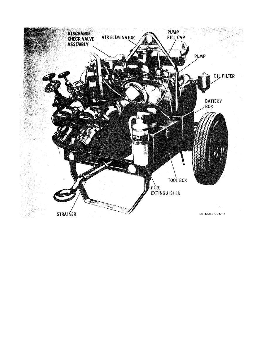
Figure 1-2. Pumping assembly, left three-quarter front view. |
|
||
| ||||||||||
|
|
 1-8. Differences Between Models
b. The engine is a V-type, four-cylinder, air-cooled,
This technical manual covers only Pumping Assem-
pressure-lubricated, four-stroke-cycle unit with an L-
bly, Peabody Barnes, Inc. Model US37ACG. No
head. Engine speed is controlled by the inter-operation
known differences exist for this model number.
of a governor and carburetor. The engine is cooled by a
flow of air, circulated over the heads by a combination
1-9. Tabulated Data
fan-flywheel enclosed in a sheet metal shroud. The
a. Identification. The pumping assembly has four
engine uses an electrcal starting motor, has magneto
identification plates, as follows:
ignition, and uses a flywheel alternator to maintain the
(1) Pump data plate. The pump data plate is
charge of the battery.
located on a bracket mounted to the discharge piping.
c. The engine and pump are secured to a two-
It indicates the pump identification number, serial
wheeled welded frame. The frame weldment consists
number, dimensions, weight, and shipping informa-
primarily of a drawbar, fixed axle, hub assemblies, and
tion.
pneumatic tires.
(2) Pump performance plate. The pump per-
d. The repair paragaphs of this manual contain
formance plate is located on the inside of the tool box
detailed descriptions of centrifugal pump compo-
cover. It indicates the pump capacities and perfor-
nents.
mances.
|
|
Privacy Statement - Press Release - Copyright Information. - Contact Us |
