 |
|||
|
|
|||
|
Page Title:
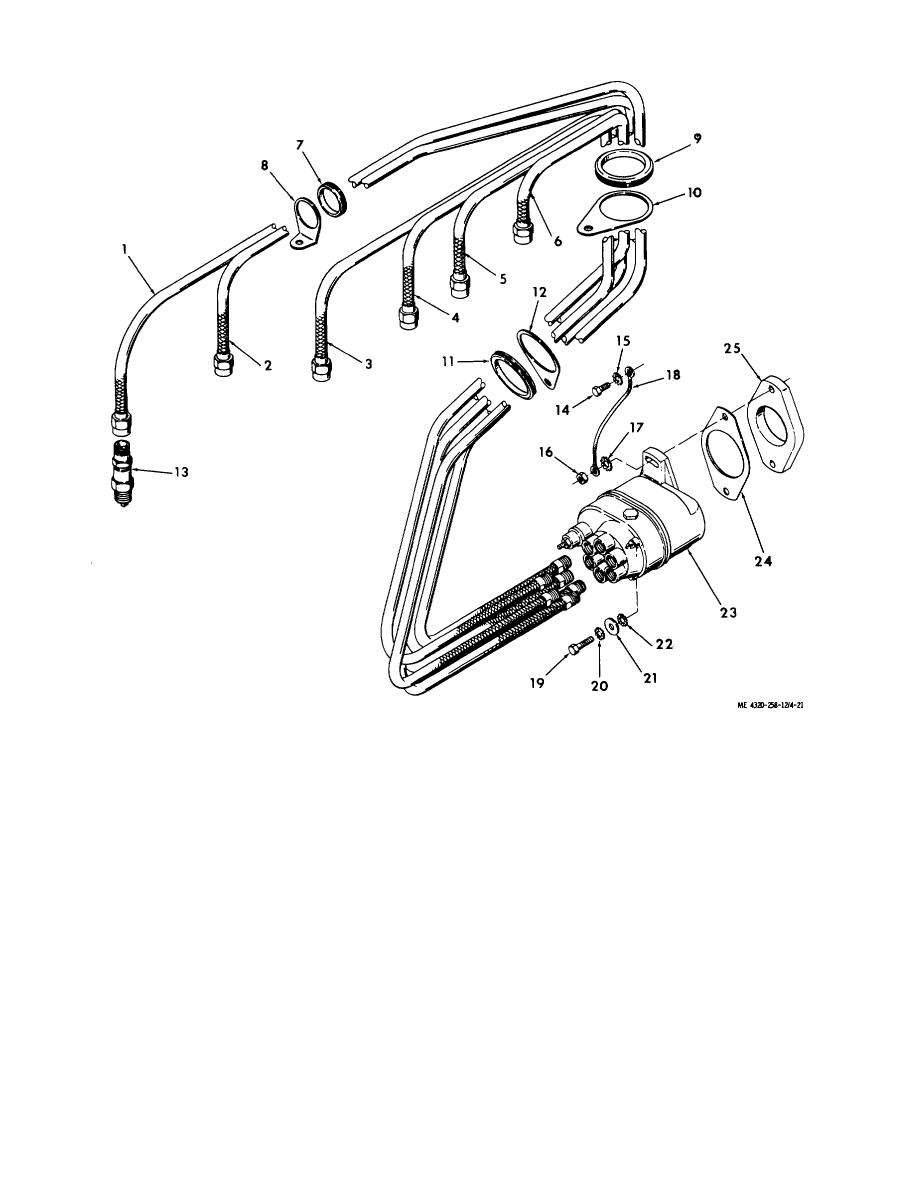
Figure 4-21. Ignition system, exploded view. |
|
||
| ||||||||||
|
|
 1.
No. 6 spark plug cable
10.
Bracket
18.
Ground strap
2.
No. 5 spark plug cable
11.
Grommet
19.
Cap screw
3.
No. 4 spark plug cable
12.
Bracket
20.
Lock washer
4.
No. 3 spark plug cable
13.
Spark plug
21.
Flat washer
5.
No. 2 spark plug cable
14.
Cap screw
22.
Lock washer
6.
No. 1 spark plug cable
15.
Lock washer
23.
Magneto
7.
Grommet
16.
Nut
24.
Gasket
8.
Bracket
17.
Lock washer
25.
Magneto spacer
9.
Grommet
Figure 4-21. Ignition system, exploded view.
(5) Remove the distributor gear (8). Remove the retaining ring (15) and use two screwdrivers inserted under
opposite sides of the rotor shaft gear (17) to pry the assembled gear and breaker cam assembly (16) from the rotor shaft
(33). The cam also acts as a key for the gear.
(6) Make sure the gear mounting surface of the rotor shaft is clean. Install the rotor shaft gear (17) and cam
assembly (16) on the shaft.
Secure with the retaining ring (15). Apply a light coat of grease on the cam lobes. The grease is provided in the breaker
point kit.
(7) Apply one drop of SAE 20 lubricating oil on the shaft bushings for the distributor gear.
4-25
|
|
Privacy Statement - Press Release - Copyright Information. - Contact Us |