 |
|||
|
|
|||
|
Page Title:
Section II. MOVEMENT TO A NEW WORKSITE |
|
||
| ||||||||||
|
|
 the building. Make sure that the diameter of the exhaust
(3) Support the discharge line at or near the
piping is large enough to prevent excessive back
pump to prevent strain.
pressure in the engine.
Warning: Do not operate the pump unit in an
enclosed area unless exhaust gases are piped to the
e. If an auxiliary fuel supply is to be used, connect
outside. Inhalation of exhaust fumes will result in
a fuel line between the source of supply and the 3-way
serious illness or death.
fuel source selector valve (1, fig. 2-4) on the fuel tank.
Operate the fuel valve to the AUX position.
d. If the centrifugal pump is operated indoors,
provide piping to carry exhaust gases to the outside of
Section II. MOVEMENT TO A NEW WORKSITE
2-3. Dismantling for Movement
charge line before disconnecting it from the pump.
Dismantle the pump for movement to a new worksite as
Drain the lines into a suitable container.
follows:
b. Remove the drain plug (fig. 1-1) from the
bottom of the pump to drain the pump housing. Catch
a. Disconnect the suction line and discharge line
the fluid in a suitable container.
from the pump. If possible, drain the dis-
c. If there is any chance of debris entering the
pump suction and discharge openings, cover the
openingwith tape.
d. If installed, disconnect the fuel line from the 3-
way fuel source selector valve (1, fig. 2-4) on the fuel
tank.
e. Disconnect any exhaust piping from the pump.
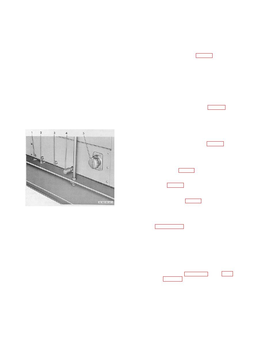
f. Drain the engine as necessary. On the left side
of the engine at the bottom of the housing are the oil
cooler drain plug (1, fig. 2-1), radiator coolant drain plug
(2), block coolant drain plug (3) and oil pan drain plug
(4). On the side of the engine is the carburetor bowl
drain plug (4, fig. 2-3).
g. When moving the pump assembly, do not
attempt to slide pump on its skid base for any long
distance. A lifting bail (fig. 1-2) is provided to facilitate
hoisting the pump onto a suitable carrier.
1. Oil cooler drain plug
4. Oil pan drain plug
2. Radiator coolant drain 5. Battery charging
2-4. Reinstallation after Movement
plug receptacle
3. Block coolant drain
Refer to paragraph 2-2 for installation instructions.
plug
Figure 2-1. Left side of engine, showing drain plugs
and charging receptacle.
Section Ill. CONTROLS AND INSTRUMENTS
2-5. General
2-6. Controls and Instruments
This section describes the various controls and
The controls necessary for operation of the centrifugal
instruments and provides the operator/crew with
pump are illustrated in figures 2-2 through 2-4 and are
sufficient information to assure proper operation of the
described in table 2-1.
centrifugal pump assembly.
2-2
|
|
Privacy Statement - Press Release - Copyright Information. - Contact Us |