 |
|||
|
|
|||
|
|
|||
| ||||||||||
|
|
 3-14. EXHAUST SYSTEM
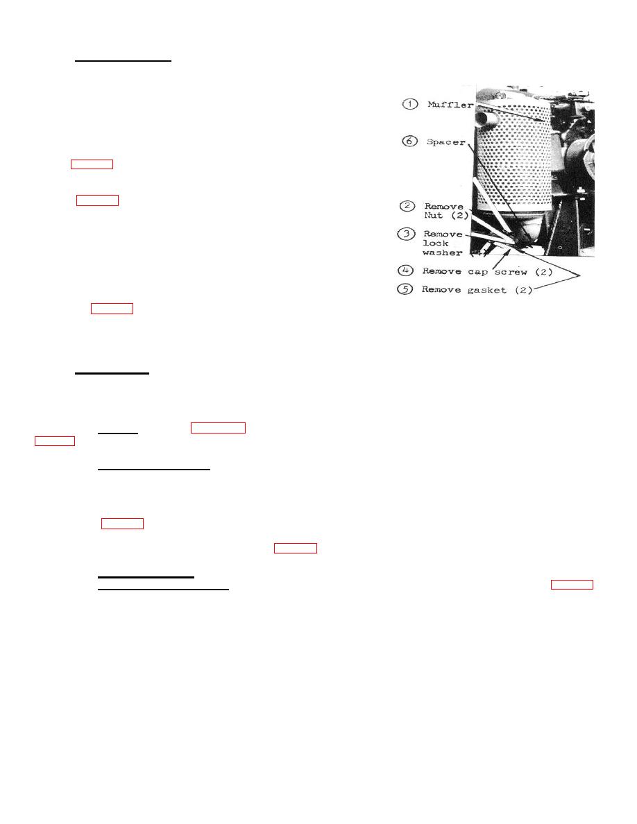
A. GENERAL - The exhaust system consists of a muffler which
connects to the manifold piping of the engine. This system tends to
equalize the pressures at which the exhaust is released, resulting in a
noise reduction. The muffler consists of a sheet-metal cylinder which
contains baffles around which exhaust gases mast circulate before they
are dispelled to atmosphere. The muffler is held in place with 2 cap
screws, with 4 lock washers and 2 nuts. There is a gasket on each side
of the spacer - spacer located between the manifold flange & the muffler
flange (Fig. 3-8).
B. REMOVAL
Refer to Fig. 3-8, and remove muffler.
C. CLEANING AND INSPECTION
1. Inspect for holes, rust, and other damage.
2. Remove rust and loose paint.
3. Repaint bare surfaces with a heat resisting paint.
4. Replace defective parts as necessary.
D. INSTALLATION
1. Always install new gaskets.
2. Refer to Fig. 3-8 and reinstall.
FIGURE 3-8. MUFFLER REMOVAL
AND INSTALLATION
3-15. FUEL SYSTEM
A. GENERAL - Refer to TM 5-2805-259-14 for a description of the engine fuel system. The components furnished
and for installed by the end item manufacturer are covered below.
B. FUEL TANK, SHUT-OFF COCK, AND FUEL LINE
a. Removal - Refer to para. 3-18 and remove pump with engine. Refer to
b. Cleaning and Inspection
1. Wash all parts with an approved cleaning solvent. Dry thoroughly.
2. Inspect for breaks, cracks, dents, loose or missing mounting hardware, damaged threads, or other defects.
3. Replace a damaged or defective tank, fuel lines or fittings.
c. Installation
1. Refer to Fig. 3-9 and install the fuel tank, lines, and fittings.
C. FUEL FILTER
a. Removal and Disassembly - Refer to Fig. 3-9 and remove the fuel filter.
Refer to TM 5-2805-259-14. and disassemble the fuel filter.
b. Clear and Inspection - Refer to TM 5-2805-259-14.
c. Reassembly and Installation - Refer to TM 5-2805-259-14 and reassemble the fuel filter. Refer to Fig. 3-9
and reinstall the fuel filter.
19
|
|
Privacy Statement - Press Release - Copyright Information. - Contact Us |