 |
|||
|
|
|||
|
Page Title:
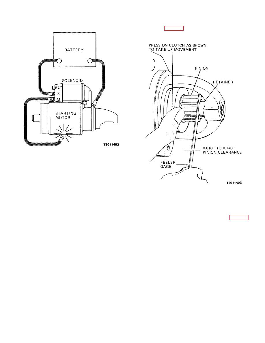
Figure 3-13. Circuit for checking pinion clearance. |
|
||
| ||||||||||
|
|
 TM 5-4320-234-34
pinion stop (fig. 3-14). The clearance shall be 0.010 to
0.140 inch (0.0250 to 0.3500 cm).
Figure 3-13. Circuit for checking pinion clearance.
(1) Disconnect the motor field coil
connector from the solenoid motor terminal and insulate
it carefully.
(2) Connect a 24-volt battery from the
Figure 3-14. Checking pinion clearance.
solenoid switch terminal to the solenoid frame.
(3) With one end of jumper connected to
c.
Starter Brush Replacement.
the solenoid motor terminal, momentarily strike the
other end against the starter frame. This will shift the
(1) Remove the through bolts (3, fig. 3-15)
drive assembly pinion into the cranking position where it
that secure the commutator end frame (4) to the starting
will remain until the battery is disconnected.
motor. Pull straight out on the end frame to disengage
the end frame bushing from the rotor shaft.
(4) Push the pinion back toward the
commutator end to eliminate slack movement. Using a
feeler gage, measure the distance between pinion and
3-16
|
|
Privacy Statement - Press Release - Copyright Information. - Contact Us |
