 |
|||
|
|
|||
|
Page Title:
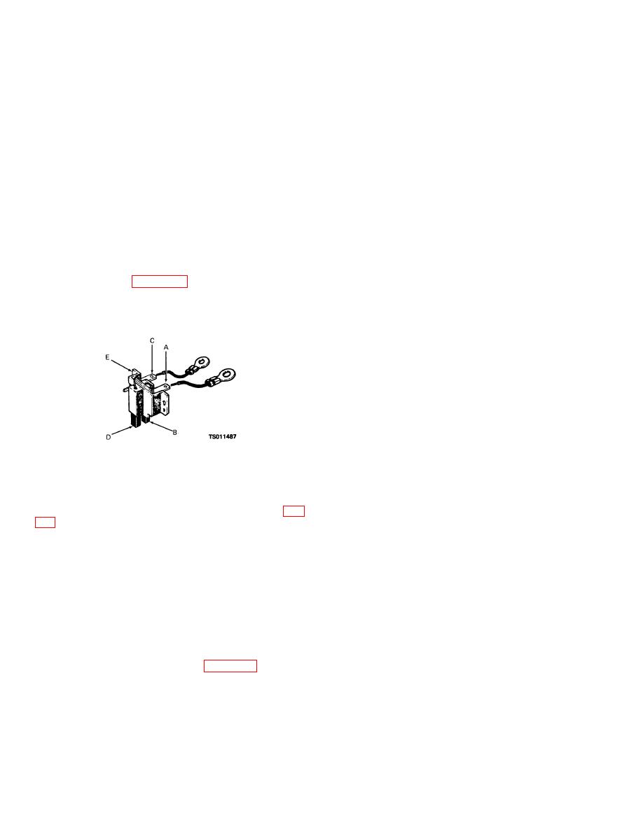
Figure 3-8. Alternator brush assembly, showing continuity paths. |
|
||
| ||||||||||
|
|
 TM 5-4320-234-34
(2) Remove the isolation diode assembly
(2) Remove the two terminal screws (7),
(26). When removing the diode assemblies, note the
nuts (8), insulating washers (9), leads (12), washers
positions of the insulating sleeves and washers to
(11), and bushings (10) from the brush cover.
ensure reassembly in proper positions.
(3) Remove the two screws (13) that
(3) Remove the square nuts (28) and
secure the insulator (14) and brush assembly (15) to the
through bolts (20) that secure the front housing (32) to
alternator; remove the brush assembly with the attached
the rear housing (41).
electrical leads (12).
(4) Using a small bladed screwdriver, pry
(4) Inspect the brush assembly for cracks,
at several points around the stator to remove the
signs of over-heating, and distortion. Check that the
assembled rotor and front housing. Do not insert the
brushes slide freely in the brushholders and that the
screwdriver blade more than 1/16 inch, or damage to
brush springs provide sufficient brush tension. Inspect
the stator windings may occur while you are separating
the brushes for cracks, oil saturation, and wear. If you
the front housing from the stator.
find that the brushes are worn to less than 3/16 inch
(0.468 cm), oil soaked, or cracked, replace the brush
(5) Clamp the front housing lightly in a vise
assembly.
and, using long nose pliers, reach through the front
housing (32) to compress the ears of the bearing
(5) If the brush assembly passes your
retainer (30) and lift it free of its recessed seat.
visual inspection, check the electrical condition of the
assembly. Refer to figure 3-8. Check that continuity
(6) With the bearing retainer free of the
exists between points A and B and between points C
recess, you can remove the assembled rotor and
and D, but that no continuity exists between point E and
bearings by tapping the end of the rotor shaft on a block
points A or C.
of wood while holding the housing.
(7) Place the assembled stator (33) and
rear housing (41) on a clean, smooth working surface
that is free of metal chips. Remove the lock nuts (34)
and insulating washers (35) that secure the studs of the
diode assemblies (36 and 37) to the rear housing (41).
Carefully push the studs out of the housing and separate
the assembled diode assemblies and stator (33) from
the rear housing.
(8) Do not disassemble the rotor unless the
bearings or slip rings are damaged and must be
Figure 3-8. Alternator brush assembly, showing
replaced. If you must remove the bearings and slip
continuity paths.
rings, proceed as follows:
(6) Use a new brush assembly if the
(a) Use a bearing puller to remove
inspection indicates faults.
the front bearing from the rotor shaft.
(7) Position the brush assembly (15, fig.
(b) Remove any sealant retaining the
rotor winding leads to the slip ring.
machine screws (13).
(8) Connect the electrical leads (12) from
slip ring terminals. Unwind the leads from the terminals,
the brush assembly to the brush cover (5) with the
taking care you do not bend or stress leads excessively.
terminal screws (7), nuts (8), insulating washers (9), and
(d) Remove the screw (42) from end
washers (11). Make sure you have the bushings (10) in
of shaft. Thread a 1/4-28 x 1-1/4-inch long screw into
place.
the slip ring hub; this process will back the slip ring
(9) Position the brush cover (5) on the
assembly (44) off the shaft.
alternator; secure with two assembled washer screws
(e) Use a bearing puller to remove
(4).
the rear bearing (45), taking care you do not damage the
c.
rotor leads.
following the sequence indicated in figure 3-7. Note the
d.
Cleaning and Inspection.
following:
(1)
Discard and replace gaskets.
(1) To remove the pulley (18), wrap the
alternator drive belt around the pulley and clamp it in a
WARNING
vise so that the belt protects pulley edges. Strike the
Clean all parts in a well-ventilated area.
end of the rotor shaft with a soft mallet or plastic
Avoid inhalation of solvent
hammer to jar loose the pulley.
3-10
|
|
Privacy Statement - Press Release - Copyright Information. - Contact Us |