 |
|||
|
|
|||
|
|
|||
| ||||||||||
|
|
 TM 5-4320-234-34
Table 2-1. Troubleshooting - Continued
MALFUNCTION
TEST OR INSPECTION
CORRECTIVE ACTION
ENGINE CONTINUED
b. If test indicates compression is low, report to next higher level of maintenance.
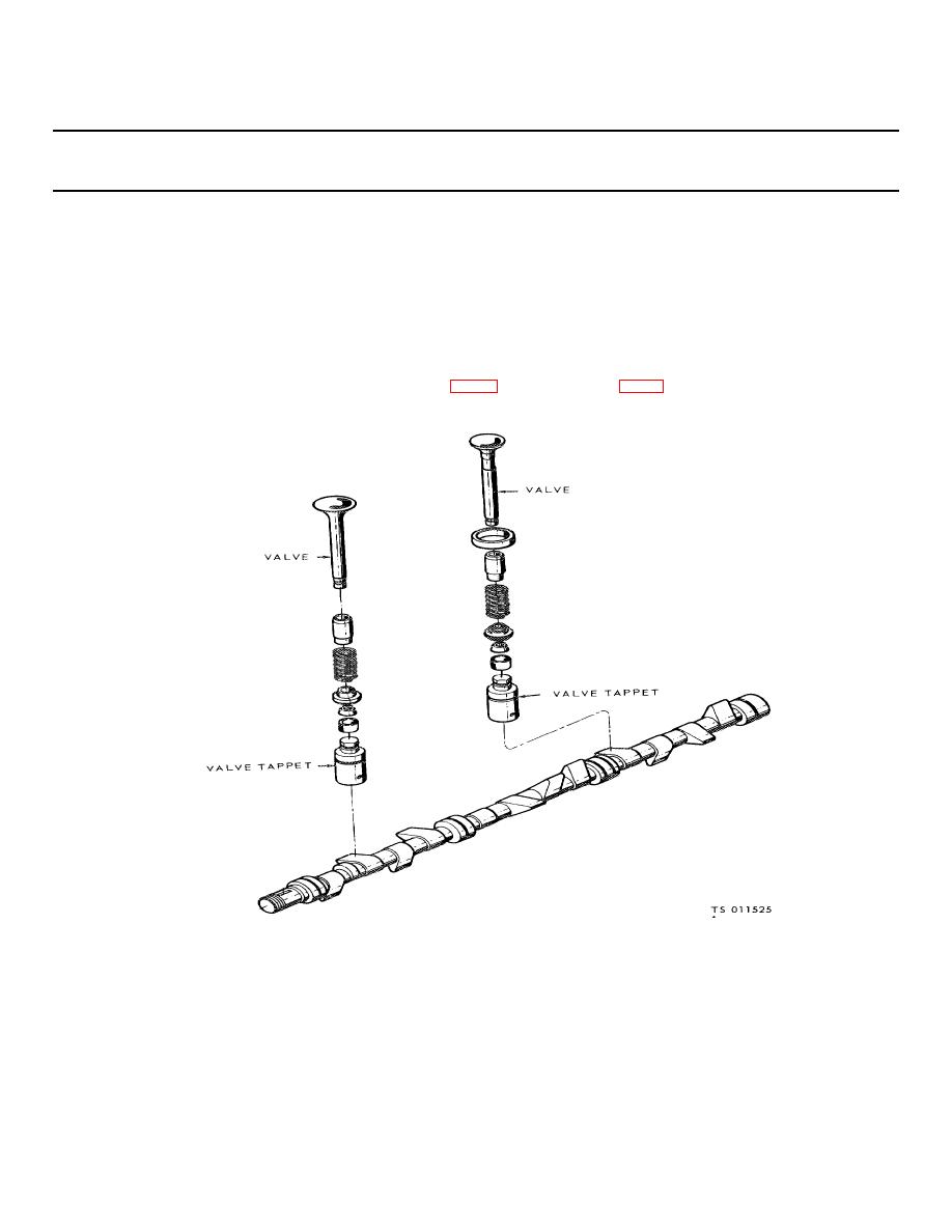
Step 3. Check for improperly adjusted valve tappets.
a. Operate engine until it reaches operating temperature.
b. Disconnect the positive crankcase ventilation valve and fittings from the valve cover.
c. Remove the nuts and washers that secure the valve chamber cover to the cylinder block. Remove the valve chamber cover and
gasket.
d. With the engine running at operating temperature and at idle speed, check the valves for proper clearance. Intake valves should
be set for 0.014 inch (0.035 cm) clearance and exhaust valves 0.016 inch (0.04 cm) clearance.
(1) Alternately pass a 0.013 inch (0.032 cm) and 0.015 inch (0.037 cm) flat feeler gage between the head of the intake valve
adjusting screw of the tappet (13, fig. 2-4), and stem of valve (2 fig 2-4).
Figure 2-4. Valve adjustment.
2-6
|
|
Privacy Statement - Press Release - Copyright Information. - Contact Us |