 |
|||
|
|
|||
|
Page Title:
Engine Overspeed Governor |
|
||
| ||||||||||
|
|
 markings, binding or sticking pointer, jammed digital hour counter, or evidence of entry of moisture. Replace a damaged
tachometer-hourmeter.
(4) Inspect the adapter for cracks, chipped or broken gear teeth, rough or catching operation, and damaged
threads; replace a damaged adapter.
(5) Inspect the tachometer shaft for kinks, broken sheathing, binding or catching rotation of the internal shaft,
and damaged threads on the coupling nuts. Replace a damaged tachometer shaft.
c. Installation. Installation is the reverse of removal; refer to figure 4-28. After installation, start the engine and
check the tachometer-hourmeter for proper operation.
4-46. Engine Overspeed Governor
a. Testing and Adjustment. The engine overspeed governor must shut off the engine when engine speed reaches
or exceeds 2700 rpm. Test and adjust as follows:
(1) Start the engine and allow it to warm to operating temperature, then shut it off.
(2) Disconnect the linkage from the engine speed governor so that the engine speed can be controlled by
manually manipulating the carburetor throttle lever.
(3) Restart the engine and have an assistant watch the tachometer. Slowly increase engine speed with no load
until the engine stops as the result of the operation of the overspeed governor or until the tachometer indicates 2750 rpm.
(4) If the engine did not shut off as the result of the tripping of the overspeed governor, you must adjust the
overspeed governor. If the engine stopped before the tachometer indicated 2650 rpm, you must adjust the overspeed
governor.
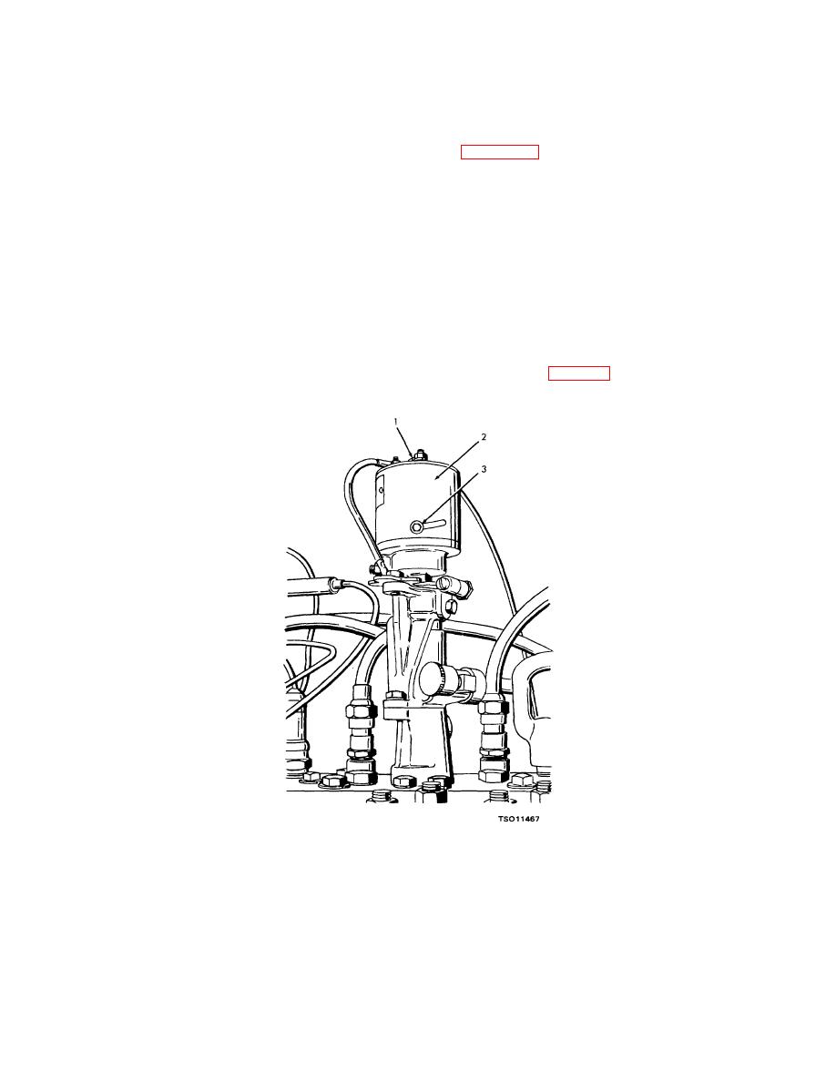
(5) To adjust the engine overspeed governor, loosen the lock screw (3, fig. 4-29) that secures the cap (2) in
position. To decrease the engine shutoff speed, rotate the cap clockwise. To raise the engine shutoff speed, turn the
cap counterclockwise. Tighten the lock screw.
1. Reset button
2. Cap
3. Lock screw
Figure 4-29. Engine overspeed governor, showing adjusting points.
(6) Recheck the speed at which the overspeed governor stops the engine as directed in steps (1) through (3) above.
Readjust
until
the
engine
4-49
|
|
Privacy Statement - Press Release - Copyright Information. - Contact Us |