 |
|||
|
|
|||
|
Page Title:
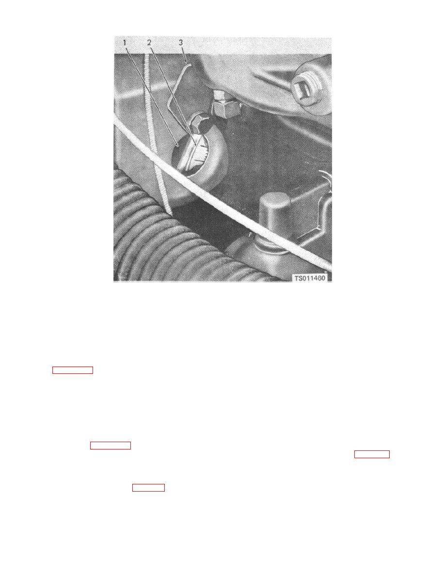
Figure 4-22. Engine timing marks. |
|
||
| ||||||||||
|
|
 1. Flywheel timing hole
2. Flywheel
3. Timing hole cover
Figure 4-22. Engine timing marks.
(3) Mount the removed magneto in a vise
, and gasket (26) on the engine with the magneto lugs
thoroughly lined with soft cloths. Insert a spark plug
engaged.
Tighten the mounting bolts moderately.
cable into distributor block hole for spark plug No. 6.
Install and connect the spark plug cables.
Refer to figure 4-20. Turn the drive lugs clockwise while
(6) Start the engine and idle it at 600 rpm. If
holding the high tension cable for No. 6 cylinder close to
the engine fails to start, it is probably due to faulty
the magneto frame so that a spark will arc when the No.
ignition timing. Recheck as directed above.
6 cable is energized. When No. 6 cable arcs, the
(7) With the engine running at 600 rpm, use a
magneto is at the No. 6 firing position. Hold the
timing light connected to the rear spark plug and check
magneto drive shaft at this position.
that the IGN-M indication on the flywheel is aligned with
(4) Check the governor drive gear to make sure
the timing pointer. If it is not exactly aligned, loosen the
that the punch-marked tooth in the cam gear is engaged
magneto mounting hardware slightly
and rotate the
between the two punch-marked teeth on the governor
magneto slightly until the correct indication is attained.
drive gear. Refer to figure 4-22.
Tighten the mounting hardware firmly.
(5) Remove the magneto from the vise. Turn
(8) Install the cover (3, fig. 4-19) on the
the magneto drive lugs of the impulse coupling
magneto with four screws (1) and lock washers (2).
counterclockwise about one-quarter turn so that the lugs
will mesh with the drive members of the governor drive
gear. Position the magneto (25,fig. 4-19), spacer (27)
4-38
|
|
Privacy Statement - Press Release - Copyright Information. - Contact Us |