|
| |
APPENDIX A
METER CLEARANCE GUIDE
CLEARANCE GUIDE
The clearances listed herein should be used as a guide in determining whether or not components need to be
repaired or replaced. Also, they should be considered as average. This means for instance, that if a nominal clearance
is .004, for manufacturing tolerances a spread from .003 to .005 is permissible. Because of this, it is possible when
checking with feeler gauges, to find at one point .003 clearance, while at another point along the same surface, the
clearance may be .005 or even .006. However, from a performance standpoint, that portion which is .003 will generally
cancel out the effect of the .005 or .006 ant average out at the nominal .004 desired. At no point should a clearance
exceed 50% of the listed maximum.
From this it should be clear that a part need not be replaced or repaired just because clearances at some point
may slightly exceed the listed maximum.
The ability of the meter to obtain acceptable repeatability and linearity for the particular operating conditions, such
as flow rate, viscosity, lubricity, abrasive contaminants, and intermittent or continuous duty, should be considered a
better guide rather than clearances alone.
For viscosities above 1000 SSU and/or temperatures above 150° F., consult the factory.
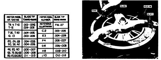
BLADE TO HOUSING CLEIRINCE
With the Blade held toward the Housing, these clearances should be maintained between the Measuring Chamber and
the full length of the edge of the Blade.
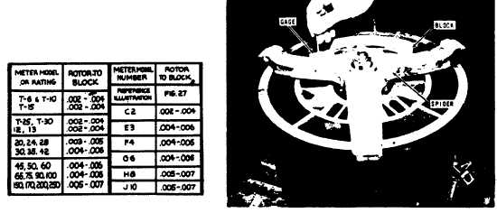
ROTOR TO BLOCK CLEARANCE
These clearances between Rotor and Block should be maintained the full length of the Rotor.
SPECIAL TOOLS REQUIRED
1. SPIDER
2. FEELER GAUGE
SPECIAL TOOLS REQUIRED
1. SPIDER
2. FEELER GAUGE
A9-40
|