|
| |
APPENDIX A
METER REVERSING PROCEDURE
To reverse meter rotation with gear trains illustrated in Figure E and Figure F, the Jack Shaft Pinion must have the same
number of teeth as the lower gear of the Idler Pinion. Thus, for the arrangement shown in Figure E, the ratio between the
Jack Shaft Pinion and the lower gear of the Idler is 1:1. In a few gear trains it is not possible to obtain the desired gear
ratio by having 1:1 between these two gears and they must have a different number of teeth to obtain the desired ratio. It
is not possible to reverse these meters (provide Left Hand Rotation) but such gear trains are usually of a special nature.
In standard meters where it is not possible to obtain the desired gear ratio with a 1:1 ratio between Jack Shaft Pinion and
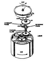
lower gear of the Idler, a Reversing Pinion is added to the gear train to provide the reversing feature. Figure A illustrates
this type of gear train for clockwise rotor rotation. Note that for this arrangement the Reversing Pinion is not part of the
gear train. When Counter-Clockwise Rotor Rotation is desired, the Reversing Pinion and Jack Shaft Pinion positions are
interchanged (See Figure B).
FIGURE A
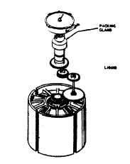
Meters with 150 PSI working pressure or led up to and
including 8" in size have only the Rotor Gear and Jack
Shaft Gear in the metered fluid as per Figure B. Meters
with 275 PSI word pressure or greater and 10" meters
and larger (regardless of pressure ratings have the
complete gear train in the metered liquid as per Figure
C.
FIGURE B
FIGURE C
A9-38
|


