|
| |
TM 10-6630-247-13&P
2-7. ASSEMBLY AND PREPARATION FOR USE - cont.
c.
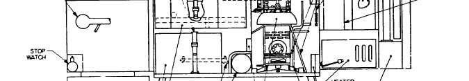
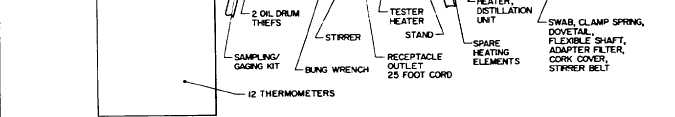
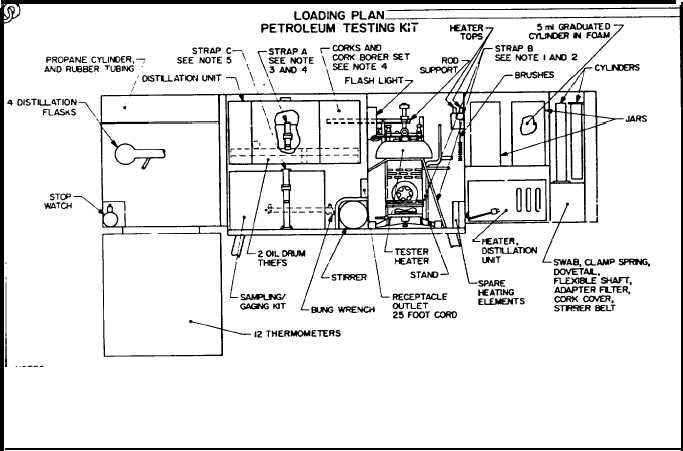
Loading Plan. Refer to figure 2-6. The loading plan supplied with the Test Kit indicates the
location of all stowed components in the cabinet. Refer to the loading plan to find the
components needed to setup and assemble the equipment.
NOTES:
1. ROUTE STRAP B BETWEEN FLASH POINT
TESTER DOME AND KATER. BUCKLE
SECURELY.
3. ROUTE STRAP A THRU 1.00 INCH
4. STOW CORK BORER SET AND CORKS, P/O
DIAMETER VENT HOLES IN REAR OF
DISTILLATION UNIT, INSIDE COOLING BATH.
DISTILLATION UNIT HOUSING, AR-
2. WRAP CORD OF TESTER HEATER AROUND
ITEMS CONTAINED INSIDE HOUSING.
5. FEED STRAP C THRU FRONT FOOTMANS LOOP,
HEATER AND REAR SUPPORT POST.
THEN SUCKLE STRAP A SECURELY.
OVER SAMPLNG GAGING KlT AND THRU LOOP
CLOSE FRONT DOOR OF
ON REAR WALL. BUCXLE SECURELY.
DISTILLATION UNIT HOUSING.
97403-13225E8524
Figure 2-6. Loading Plan.
2-16
|