 |
|||
|
|
|||
|
Page Title:
Attach Filler/Discharge Assemblies, Hoses and Gate Valves |
|
||
| ||||||||||
|
|
 TM 10-5430-239-12&P
0005 00
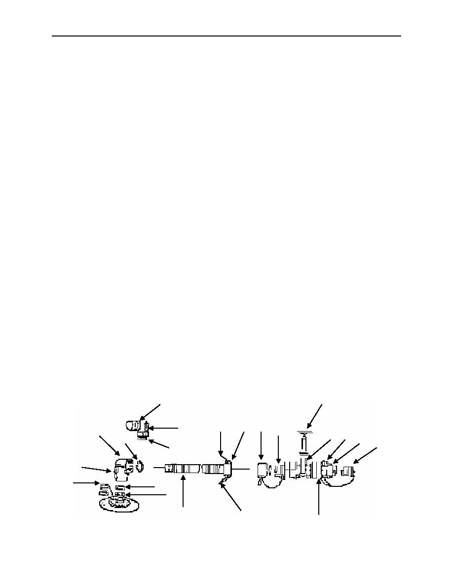
Attach Filler/Discharge Assemblies, Hoses and Gate Valves
1. Remove dust caps (1) from male coupling halves (2). If sealing surfaces of male coupling halves (2)
are dirty, wipe clean with a clean rag.
2. Check to see that gaskets (3) are in place in filler/discharge elbows (4, 5) and correctly seated.
3. Insert elbows (4, 5) over male coupling halves (2) and close both cam-lever arms (6) on each elbow
(4, 5) at the same time, by hand.
NOTE
Female/Female elbow is used during fill operation.
Female/Male elbow is used during discharge operation.
4. Select one filler/discharge elbow (4 or 5) to be used in operation. Place dust cap on elbow (4 or 5)
that will not be used.
NOTE
If installing hose on female elbow, perform step 5. If installing hose on male
elbow, go to step 6.
5. Insert male end of hose (7) in elbow (4). Close both cam-lever arms (8) on elbow (4) at the same
time, by hand, to lock hose (7) into place.
6. Insert female coupling half (9) of hose (7) on elbow (5). Close both cam-lever arms (10) on coupling
half (9) at the same time, by hand, to lock hose (7) into place.
7. If performing fill operation, remove dust cap (11) from male coupling half (12) on gate valve (13).
Insert female end of hose (7) in female coupling half (15). Close both cam-lever arms (16) at the
same time to lock the gate valve (13) into place.
8. If performing discharge operation, remove dust plug (14) from female coupling half (15) on gate valve
(13). Insert male end of hose (7) in female coupling half (15). Close cam-lever arms (16) at the same
time, by hand, to lock the gate valve (13) into place.
9. Close gate valve (13) by turning hand-wheel (17) to the full clockwise position.
17
5
10
9
11
6
12
4
13 16
15
3
14
3
8
1
3
2
7
10
16
0005 00-12
|
|
Privacy Statement - Press Release - Copyright Information. - Contact Us |