 |
|||
|
|
|||
|
Page Title:
Installation of Vent Pipe Assembly |
|
||
| ||||||||||
|
|
 TM 10-5430-238-12&P
0005 00
4. Apply sealing compound (Item 8, WP 0040 00) to the threads of drain hose (4).
5. Install drain hose (4).
6. Apply sealing compound or anti-seize tape (Item 7, WP 0040 00) to threads on other end of drain hose
(4).
WARNING
Check that the drain gate or ball valve has been rotated clockwise to the closed
position before proceeding. Failure to close the valve handle can cause loss of
fuel and possible fire or explosion.
7. Install ball valve or drain gate valve (5) onto the end of drain hose (4).
NOTES
A narrow, shallow drainage trench, placed at the outer edge and away from the tank,
should be used as an extension for the drain hose, drain gate, or ball valve.
Installation of drain plug and drain assembly are applicable to all tanks except for 3,000-
Gallon (11,360 liter) tanks.
8. Return the tank end to the flat position, laying drain hose (4) and ball valve or drain gate valve (5) in
narrow, shallow drainage trench.
Installation of Vent Pipe Assembly
CAUTION
Prior to installing the fuel tanks, check all coupling gaskets and sealing
surfaces to ensure they are in place and serviceable.
NOTE
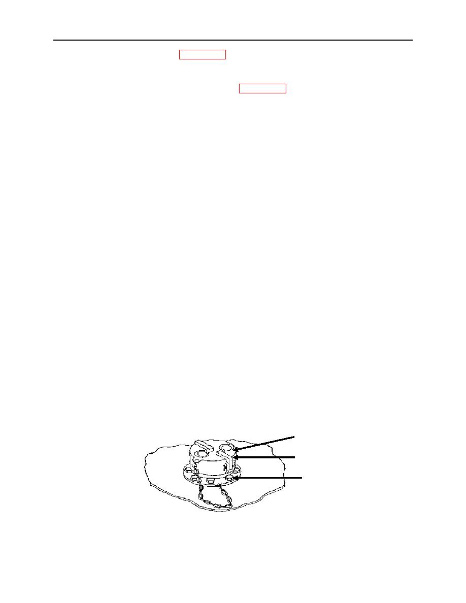
Dust cap is chain-attached to prevent loss.
1. Remove dust cap (1) by pulling cam-lever arms (2) outward, and lifting up on dust cap (1).
2. Torque dust cap screws (3) to 30 in-lb (3.41 Nm).
1
2
3
0005 00-9
|
|
Privacy Statement - Press Release - Copyright Information. - Contact Us |