|
| |
TM 10-5430-237-12&P
0005 00
0005 00-8
NOTE
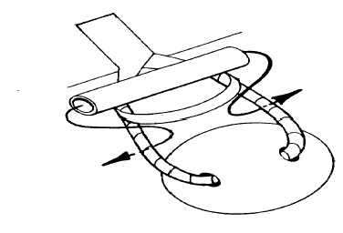
There are two fill/discharge fittings which provide a 2-inch (50.8 mm) coupling
located at opposite ends of the tank. One end provides a female cam-lock
coupling; the other end provides a male cam-lock coupling. Either, or both,
may be used for filling the tank.
3. Remove the dust plug from the female cam-lock coupling (6) or the dust cap from male cam-lock
coupling (7) by pulling out on cam-lever arms.
4. Depending on system setup connect water fill/discharge lines to the fittings; secure by pushing cam-
lever arms in against hose, or fill tank through top opening.
NOTE
Do not exceed capacity of tank. If metering gauge is not available, tank is full
when water level reaches lower edge of the tank collar.
5. Begin filling the tank. A maximum of 3,000 gallons (11,356 liters) may be put into the tank.
6. Turn off flow of water when tank is full.
7. Disconnect supply line from the tank, and stop the flow of water by installing the dust plug in the
female cam-lock couplings (6) or the dust cap on the male cam-lock coupling (7).
OPERATING PROCEDURES (Filling the Tank) MODELS GTA-Z60TPW and 3-K-W-O-A/Z
NOTE
There are two fill/discharge fittings which provide a 2-inch (50.8 mm) coupling located
at opposite ends of the tank. One end provides a female cam-lock coupling; the other
end provides a male cam-lock coupling. Either, or both, may be used for filling the tank.
1. Remove the dust plug from the female cam-lock coupling (6) or the dust cap from male cam-lock
coupling (7) by pulling out on cam-lever arms.
2. Depending on system setup, connect 2” ball valve assembly to the fittings; secure by pushing cam-
lever arms in against hose.
3. Attach hose to 2” ball valve assembly. Open ball valve assembly.
Models 90074/91038/
GTA-Z60TPW only
|